Showing posts with label STRIP FOUNDATIONS. Show all posts

Friday, January 11, 2013

Sizing of the Design: Continuous Beam Strips.

The sizing of the rectangular beam is similar to the sizing of the upstand beam of the inverted T, i.e. based mainly upon bending moments and shear forces. However, the beam width must in this case satisfy that required for allowable bearing pressure criteria for the full contact area of the beam.

For inverted T beams the bearing stresses are reduced to an acceptable amount by the use of the ground strip forming the flange of the inverted T.

The main rib of the T beam is then determined from the design requirements for longitudinal bending and shear forces keeping a reasonably standard profile for shutter reuse to make the beam economic. The flange thickness and reinforcement is determined from the bending moments and shear forces acting on the cantilever slab/flange (see Fig. 11.35).

Casting of the beam is usually carried out in two lifts, the ground slab being cast up to the top of the flange leaving a roughened surface with the cage reinforcement projecting.

The main beam is then cast on the cleaned surface of the slab up to its top level (see Fig. 11.36).

Inverted Tee beam – typical loads, moments and reinforcement.
Fig. 11.35 Inverted Tee beam – typical loads, moments and reinforcement.

Typical casting stages for inverted Tee beam.
Fig. 11.36 Typical casting stages for inverted
Tee beam.

Design Decisions: Continuous Beam Strips.

The economic design of continuous beam strips can be greatly affected by the choice of curtailment of the
lengths of beams.

They are generally used where longitudinal bending moments are a major problem for the foundation design, i.e. in variable ground, soft sub-strata, or where loading is variable in the length of the beam. They are also used in some areas of mining activity etc., where bending from differential subsidence movement is critical but where tensile and compressive ground strains in the foundation can be controlled.

The decision to use a continuous beam strip usually follows the need to

(1) Reduce differential settlements below framework columns.
(2) Combine foundations which would otherwise tend to overlap.
(3) Ease construction by the use of continuous strips rather than separate pads when they are becoming closely spaced.

The decision to use an inverted  T rather than a simple  rectangular beam would result from bearing pressure
criteria demanding excessive beam widths for bearing when compared to widths required to resist bending and shear.

Rectangular and tee-beam Continuous Strips.

Introduction
Rectangular beam strips are briefly discussed previously and the inverted  T-beam strip in section 9.3.7 where it is mentioned that the main difference in the two beam foundations relates to the relationship between the width of beam required to resist bending moments and shear forces and that required to achieve the allowable bearing pressures.

If the two widths are similar then the rectangular beam tends to be economic. However, on relatively poor-quality sub-strata the beam width required to achieve the allowable bearing pressures often far exceeds that required for bending and shear resistance. In the latter case it tends to prove economic to reduce the beam width and spread the load through a flange slab on the soffit of the beam.

1 Design decisions   The economic design of continuous beam strips can be greatly affected by the choice of curtailment of the lengths of beams. They are generally used where longitudinal...

2 Sizing of the design   The sizing of the rectangular beam is similar to the sizing of the upstand beam of the inverted T, i.e. based mainly upon bending moments and shear forces. However, the beam width...

Wednesday, January 9, 2013

Design Example 3: Reinforced Strip Foundation.

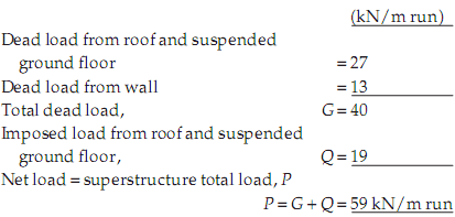
The load-bearing wall of a single-storey building is to be supported on a wide reinforced strip foundation.

A site investigation has revealed loose-to-medium granular soils from ground level to some considerable depth. The soil is variable with a safe bearing capacity ranging from 75–125 kN/m2. Also some soft spots were identified, where the bearing capacity could not be relied upon.

The building could be supported on ground beams and piles taken down to a firm base, but in this case the solution chosen is to design a wide reinforced strip foundation  capable of spanning across a soft area of nominal width.

To minimize differential settlements and allow for the soft areas, the allowable bearing pressure will be limited to na = 50 kN/m2 throughout. Soft spots encountered during construction will be removed and replaced with lean mix concrete; additionally, the footing will be designed to span 2.5 m across anticipated depressions. This value has been derived from the guidance for local depressions given later on raft foundations. The ground floor slab is designed to be suspended, although it will be cast using the ground as permanent formwork.

Loadings

If the foundations and superstructure are being designed  to limit state principles, loads should be kept as separate unfactored characteristic dead and imposed values (as above), both for foundation bearing pressure design and for serviceability checks. The loads should then be factored up for the design of individual members at the ultimate limit state as usual.

For foundations under dead and imposed loads only,  factoring up loads for reinforcement design is best done  by selecting an average partial load factor, γP, to cover both dead and imposed superstructure loads from Fig. 11.22 (this is a copy of Fig. 11.20 Reinforced concrete strip design conditions.).

Combined partial safety factor for dead + imposed loads.
Fig. 11.22 Combined partial safety factor for dead + imposed loads.


From Fig. 11.22, the combined partial safety factor for superstructure loads is γP = 1.46.

Weight of base and backfill, f = average density × depth
                                             = 20 × 0.9
                                             = 18.0 kN/m2

This is all dead load, thus the combined partial load factor for foundation loads, γF = 1.4.

Sizing of foundation width
New ground levels are similar to existing ones, thus the (weight of the) new foundation imposes no additional  surcharge, and may be ignored.

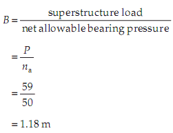
The minimum foundation width is given by


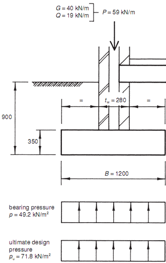
Adopt a 1.2 m wide × 350 mm deep reinforced strip foundation, using grade 35 concrete (see Fig. 11.23).

 Fig. 11.23 Reinforced strip foundation design example – loads and bearing pressures.

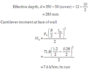
Reactive upwards design pressure for lateral reinforcement design
Lateral bending and shearb = 1000 mm.


Thus vu < vc , therefore no shear reinforcement is required.

Loading for spanning over depressions
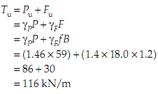
Where a local depression occurs, the foundation is acting like a suspended slab. The ultimate load causing bending and shear in the foundation is the total load i.e. superstructure load + foundation load, which is given by


Longitudinal bending and shear due to depressions
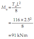
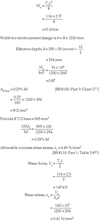
Ultimate moment due to foundation spanning – assumed simply supported – over a 2.5 m local depression is

Width for reinforcement design is b = B = 1200 mm.
Thus vu < vc = 0.49 N/mm2, therefore no shear reinforcement is needed.

Depression at corner of building
The previous calculations have assumed that the depression is located under a continuous strip footing. The
depression could also occur at the corner of a building where two footings would meet at right angles. A similar calculation should then be carried out, to provide top reinforcement for both footings to cantilever at these corners.

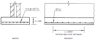
Fig. 11.24 Reinforced strip footing design example – reinforcement.

Design Decisions - Sizing up of the Design - Reinforced Concrete Pads and Strips..

Design decisions
The decision to reinforce a concrete foundation of this type usually follows the realization that the ground conditions are variable and/or deep trench fill is uneconomic.

Reference to (Table 10.2 Foundation selection to suit varying site conditions) on choice of foundation types will assist in this decision.

Sizing up of the design
The depth and width of the reinforced concrete strips are determined in a similar way to that adopted for unreinforced strips and trench fill. The depth to the underside of the footing is determined by the ground conditions and the level of suitable sub-strata, taking into account the need to be below the effect of any critical frost heave or swelling and shrinkage of sub-strata.

The fabric reinforced strip is used generally where there is both relatively poor ground and smallish loads or where some slight movements are expected from differential  settlement or subsidence.

More heavily reinforced strips, using bars and not fabric, are used where ground conditions are more critical and/or loading more excessive (see Fig. 11.21).


Fig. 11.21 Section through reinforced strip.

For particularly heavy loads and/or poor ground, beam strips are often used.

For axially loaded strip foundations, the breadth of the strip required is:
where P is the superstructure load/unit run and na is the net allowable bearing pressure.

The thickness of the foundation should be determined by designing for the cantilever action of the strip taking into account the bending, shear and bond stresses to be accommodated and allowing for the longitudinal moments and forces (see Fig. 11.20 Reinforced concrete strip design conditions.).

For strip footings a generous thickness for bending is  necessary in order to maintain the shear and bond stresses within permitted limits and in order to produce an economic balance for the ratio of concrete to reinforcement.

The detailed design of a reinforced concrete strip is covered in Design Example 3 which follows, but in general the  calculated foundation thickness required for shear and bending compression is rounded up to the nearest 50 mm as the economic thickness for the strip foundation.

Reinforced Concrete Pads and Strips.

Introduction
These pads are used in similar locations to those of the mass concrete pad, but where the reduction in cost of mass concrete exceeds the cost of the additional labour and materials.

These extras would include providing the reinforcement and any extra shuttering, blinding, or working space which may prove necessary for the reinforced solution.

The plan size and shape is determined from the vertical load and allowable bearing stress in conjunction with any physical requirements. The depth and amount of reinforcement is determined from the resulting bending moments and shear force considerations (see Fig. 11.20) or from  past experience. The experience basis is often used where reinforcement needs are related to variable ground for a familiar location and use or where there is a need to  cater for a number of time-related variations in differential settlement.


1 Design decisions and Sizing up of the design   Design decisions The decision to reinforce a concrete foundation of this type usually follows the realization that the ground conditions are variable and/or deep trench fill is...

2 Design Example 3: Reinforced strip foundation   The load-bearing wall of a single-storey building is to be supported on a wide reinforced strip foundation. A site investigation has revealed loose-to-medium granular soils...

3 Design Example 4: Reinforced pad base  The axially loaded pad base in Design Example 2 is to be redesigned as a reinforced base, founded in the weathered sandstone. Assuming settlements have been judged to be...


Reinforced concrete strip design conditions.
Fig. 11.20 Reinforced concrete strip design conditions.

Unreinforced Concrete Strips.

The unreinforced strip footing requires slightly better ground conditions than trench fill to maintain trench stability during construction of the masonry over it.

The adoption of a thin strip means that the trenches tend to remain open longer during construction than in the case  of the trench fill solution to allow bricklayers or masons to work from within the trenches. However, the overall cost of the work often proves less than for trench fill and on many sites proves to be easily achieved. It has the added advantage of more easily accommodating services but suffers  similar disadvantages to trench fill in active mining areas.

The choice between trench fill and concrete strips usually depends upon cost.

The width of the strip is generally the nearest suitable excavation standard bucket width to that of the design
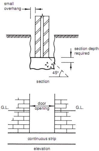
width required from the calculations. However, for deep strips the working space required for bricklayers can  determine the width required. The thickness is generally selected to be greater than the overhang (i.e. this is based upon a 45° dispersion of load through the mass concrete, see Fig. 11.18).

 Fig. 11.18 Unreinforced strip.

Where this guidance would give a thinner strip than that practical from a construction point of view, or that desirable from a performance requirement, a greater nominal thickness is used. Longitudinal bending considerations, particularly where the strip requires to be continuous below door openings etc. (see Fig. 11.19), is one of the situations which may demand a thicker strip than that given  by the general 45° line. However, this would only apply if dispersion of load along this length of footing is required to reduce the bearing pressure.

Fig. 11.19 Continuous strip through opening.

Design Example: Trench Fill Strip Footing.

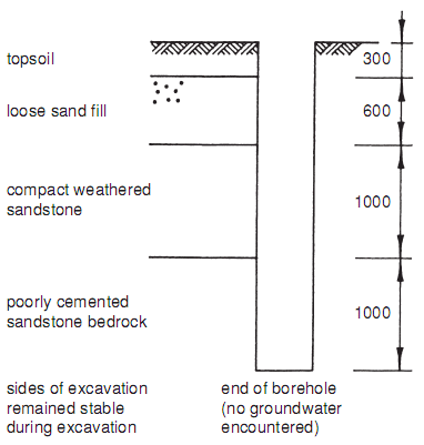
The internal load-bearing wall for a four-storey office block is to be supported on a strip foundation. Borehole investigations produced the consistent soil profiles shown in Fig. 11.13.

Soil analysis shows that the sand fill is an unreliable bearing strata. The weathered sandstone has net allowable bearing pressures of na = 400 kN/m2 for strip footings and na = 550 kN/m2 for pads, both with a maximum of 20 mm settlement. The sandstone bedrock has a net allowable pressure of na = 2000 kN/m2
for pad foundations.

By inspection of the soil profile and analysis in Fig. 11.13, the strip will be founded in the compact weathered sandstone. The relatively even distribution of the loading will not lead to unacceptable differential settlements and, as the sides of the excavations do not collapse in the short-term, mass concrete trench fill footings have been selected as the most appropriate foundation type.

Fig. 11.13 Borehole log for Design Examples 1, 2 and 4.

Loadings
The loadings from the four-storey structure have been  calculated (as working loads) as follows.


Size of base (normal method)
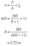
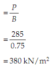
The foundation surcharge is considered small enough to be neglected. The minimum foundation width is given by


In many instances this approximate method is satisfactory.

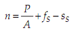
Where the new foundation surcharge is large, or the allowable bearing pressure is low, the following method should be used.

Size of base (allowing for foundation surcharge)
Dead load from new surcharge

Imposed load from new surcharge


The weight of the new foundation is taken as approximately equal to the weight of soil displaced, and thus is
excluded from the above loads.

The net bearing pressure is

In this case the existing surcharge sS = 0.


As may be seen, the normal method value of B = 0.71 m in this example is sufficiently accurate for all practical purposes.

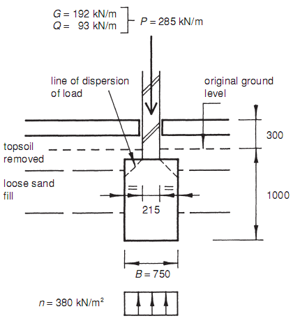
Final selection of foundation width must take into account the width of the wall, together with an allowance for tolerance. It should also try to suit standard widths of excavator buckets which are in multiples of 150 mm, e.g. 450 mm,  600 mm, 750 mm, etc. In this case a width of B = 750 mm would be appropriate, as shown in Fig. 11.14.

Actual net bearing pressure (ignoring foundation surcharge)

The actual net bearing pressure beneath the strip footing may now be calculated, if required.


Fig. 11.14 Trench fill strip footing design example.

Trench Fill Foundation Design Decisions.

A typical trench fill foundation is shown in Fig. 11.7 where (a) indicates a typical section, (b) shows the typical design forces, and (c) illustrates the possible externally applied ground strains which can prove critical. Such strains can and do cause serious damage to buildings and their finishes.

The considerations to be made therefore in the design decisions relate to:

(1) The depth and type of suitable ground-bearing strata relative to foundation loading.

(2) The likelihood of large horizontal ground strains due to moisture changes in the sub-strata, mining activity or frost.

(3) The economy of trench fill versus normal strip footings.

Fig. 11.7 Trench fill conditions.
 
Considering (1), strip footings can prove economic for medium loads at shallow-to-medium depths on firm-to-stiff sub-strata, for example, 100–300 kN/m2 at 600–1500 mm deep on firm-to-stiff clay, firm-to-dense sand or firm-to-stiff sandy clay or clayey sand.

Considering (2), provided that the sub-stratum is not  a sensitive clay, i.e. not highly shrinkable, and provided that there is no likelihood of large ground strains from  mining or other activities, then trench fill footings should  be considered. Standard trench strips should generally be avoided where lateral forces may be picked up from below ground on the sides of the footing. A void or cushion can however be adopted to prevent the transfer of such forces where this is appropriate. Alternatively, the foundation and its superstructure may, in certain circumstances, be designed to resist the force transferred.

Considering (3), the economics of any potential solution vary with time and are dependent on:

(a) Material costs and availability,
(b) Excavation technology and machinery,
(c) Weather conditions and likely stability of trenches, and
(d) Manpower availability and other conditions relating to a particular site.

As a general rule providing that the trenches can remain stable for a suitable period to allow excavation and casting of concrete, and that conditions (1) and (2) are appropriate, then trench fill should be considered in any comparison exercises, particularly if the width of a normal strip footing would be dictated by the working space required for brick- laying below ground.

Under such conditions, the solution is likely to prove  competitive both from a cost point of view and speed of construction. The speed of construction can be particularly important where trench stability is time related and where foundations are being constructed through a winter period.

Under such conditions a mass concrete trench fill could  be adopted. However, the use of stone or concrete is an  economic decision based upon the ground conditions,  the long- and short-term stability of the trenches, and the availability of the materials (see Table 10.2).

Table 10.2 Foundation selection to suit varying site conditions

Trench Fill Strips.

A brief description of trench fill strips is given previously. The design of such strips is relatively simple, and it is true to say that there is more design involved in making the decision to adopt such a foundation than in analysing and sizing the appropriate trench fill.

Trench fill is often used in an attempt to:

(1) Reduce the foundation width where brickwork below ground would need a wider footing to suit working space,

(2) Reduce the labour content of construction, and

(3) Speed up the construction of the footing, for example, in conditions where trench supports are not necessary for short periods but would be required if the trench were left open for a significant time.

The saving in excavation, labour, time and/or temporary works can in some situations be quite considerable. However, in loose ground the quantity of concrete used can become both difficult to predict and/or considerable in quantity particularly if trenches meet or cross at right angles.

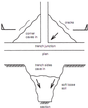
Strips excavated through poor ground to reach suitable bearing strata can prove troublesome due to instability of the trench sides, particularly at changes in direction of the strip (see Fig. 11.1). This can be overcome by using suitable trench supports. However, the problem can often be more economically assisted by good design.

Fig. 11.1 Trench instability at change in direction.

For example, Fig. 11.2 shows two alternative designs for the same house foundations: in (A) the trenches would fail under much less critical conditions than the trenches in (B) since this scheme avoids trench direction changes and hence avoids the corner failure conditions of the trench sides.


Fig. 11.2 Trench fill alternatives.

A disadvantage in some situations is the tendency of the trench strips to pick up, via passive resistance, any longitudinal or lateral ground strains which may occur in the strata around the foundation. This can prove to be a major problem in active mining areas and in sub-strata sensitive to moisture changes such as shrinkable clays. In some situations this problem can be overcome by the insertion of a compressible batt against the trench faces (see Fig. 11.3),  but this must be considered for all directions and for conflicting requirements since passive resistance is often exploited in the superstructure and foundation design.


Fig. 11.3 Trench fill with compressible side formers.

In addition the high level of the concrete can create problems for drainage and services entering the building if these are not pre-planned and catered for. The top surface should be low enough so as not to interfere with landscaping and planting. In some situations concrete trench fill can create undesirable hard spots, and stone trench fill should be  considered.

Stone trench fill used under the strip loads to transfer the loads to the lower sub-strata is more yielding than concrete trench fill which may produce excessive differential movement between the main strip load area and the general slab (see Fig. 11.4).


Fig. 11.4 Stone versus concrete trench fill.

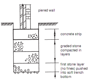
In soft wet conditions, the soft materials at the surface of the trench bottom can be absorbed into the voids of a first layer of no fines stones blinded by a second layer of well graded stone. The second layer prevents the soft materials from oozing up through the hardcore. This can prove to be a clear advantage for difficult sites where the material is  sensitive and wet and where good clean trench bottoms are difficult or impractical to achieve. By this method a stable trench fill can quickly and easily be achieved in relatively poor ground (see Fig. 11.5).

Fig. 11.5 Trench fill in poor ground.

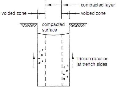
Compaction difficulties can be experienced in narrow trenches cut in dry or relatively stiff sub-strata where
compaction of the fill at the edges is partly restricted by the frictional resistance of the trench sides. This tends to show itself in the concave surface of the compacted layer (see  Fig. 11.6). However, this can be overcome by using suitably graded stone in relatively thin layers and by extra com- paction at the edges of the trench.


Fig. 11.6 Concave compacted surface.

Selection of suitably graded and shaped stone is particu- larly important, for example, single sized rounded stone will tend to compact automatically during filling in a sim- ilar way to say filling a trench with marbles. The marbles immediately fall into contact on more or less the maximum compaction due to the standard radius involved. However, in some locations it is important to avoid forming a field drain within the fill which may attract moving water, therefore well graded material is essential in these situations.

Unreinforced Concrete Pads and Strips.

In general, shallow pads and strips are the economic foundation for most structures where ground conditions allow this solution.

The suitability of shallow strips and pads should be one of the first considerations for the engineer and their use tends to form the  normal  foundation criteria against which the extra over cost of abnormal foundations tends to be judged.

This does not mean however, that strips and pads should be used wherever possible since as they become deeper or more heavily reinforced the alternatives of vibrocompaction and/or piles becomes competitive.

However, at shallow depth, they are the economic alternative.

1 Trench fill   A brief description of trench fill strips is given previously. The design of such strips is relatively simple, and it is true to say that there is more design involved in making the decision to

2 Trench fill design decisions   A typical trench fill foundation is shown in Fig. 11.7 where (a) indicates a typical section, (b) shows the typical design forces, and (c) illustrates the possible externally applied ground...

3 Sizing of the design   In the case of mass concrete trench fill the foundations can be sized using the assumptions that dispersion of load through the strip can be assumed to be at an angle of 45°. In the case...

4 Design Example 1: Trench fill strip footing   The internal load-bearing wall for a four-storey office block is to be supported on a strip foundation. Borehole investigations produced the consistent soil profiles shown in Fig. 11.13. Soil...

5 Design Example 2: Deep mass concrete pad base   A steel-framed building is to be built on a site adjoining previously, where variable fill extends down to the level of the bedrock. A heavily loaded stanchion, carrying axial load only, is to be supported on a...

6 Unreinforced concrete strips   The unreinforced strip footing requires slightly better ground conditions than trench fill to maintain trench stability during construction of the masonry over it. The adoption of a thin...

Wednesday, December 19, 2012

Inverted T Beam Strips.

The inverted T beam strip fulfils the same function as the rectangular beam strip but the cross-section is modified to an inverted T so that the flanges reduce the contact pressure on the ground (see Fig. 9.9).

Fig. 9.9 Inverted beam strip.

Rectangular Beam Strips.

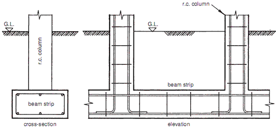
Rectangular beam strips consist of rectangular reinforced ground beams which are designed to be of sufficient width to reduce the bearing pressures on the sub-strata to an acceptable value. The beam is required to be of sufficient cross-section to resist the induced bending moments and shear forces in the longitudinal direction. The beam is reinforced with either ladder reinforcement or caged reinforcement to suit the design conditions. Figure 9.8 shows a typical beam strip supporting point loads.

Fig. 9.8 Typical beam strip.

Stone Trench Fill.

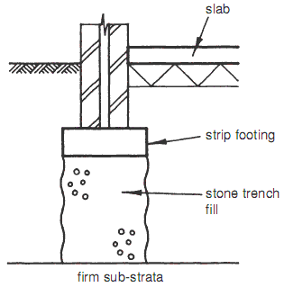
Stone trench fill consists of stone deposited into the open trench excavation and compacted in layers. It is particularly useful in areas where poor quality sands, sandy silts, etc., exist. The material immediately below the topsoil is often suitable for the general floor slab loading but not for the more heavily loaded external and internal strip loadings.

Suitable sub-strata for the strip loads often exists at a  shallow depth and stone trench fill can be used down to these levels (see Fig. 9.7).

Fig. 9.7 Stone trench fill.

Concrete Trench Fill.

Concrete trench fill consists of a mass concrete strip cast into the open trench making use of the trench sides as a shutter (see Fig. 9.5).

Concrete trench fill is often used where strip loads are required to be transferred to relatively shallow depths
through soft material which is capable of standing up, without extra support, for at least a period adequate to cater for the construction sequence to be adopted. The trench fill can embrace requirements for heavy loads going down to rock or light loads on soft sub-strata (see Fig. 9.6).

The requirement for working space within the trench  for bricklayers is not a factor in determining the width of excavation with this method. Pouring concrete to within 150 mm of ground level overcomes this consideration.

Fig. 9.5 Concrete trench fill.


Fig. 9.6 Concrete trench fill.

Concrete Strips – Plain and Reinforced.

The concrete strip footing replaced the corbelled masonry in more recent constructions. In plain (unreinforced) strip footings the thickness is determined by the requirement for the line of dispersion to pass through the side of the footing as shown in Fig. 9.1. The width of the trench must also allow working space for the bricklayers to build the masonry off the footing.

The profile of the reinforced concrete strip is similar to the unreinforced strip except that it can generally be made thinner in relation to its projections since it no longer relies upon an approximate 45° line of load dispersion. The strip is often reinforced with a fabric or lattice reinforcement.

The longitudinal bars are the main bars selected to suit the longitudinal bending expected on the strip and the cross bars designed to cater for the cantilever action on the projections (see Fig. 9.4).

Fig. 9.1 Typical strip footing.

Fig. 9.4 Reinforced strip footing.

Friday, December 14, 2012

Masonry Strips.

Masonry strips are rarely used these days, however they can be adopted where good quality sub-strata exists and the raw materials for masonry construction are cheap and abundant. The wall is increased in width by corbelling out the masonry to achieve the required overall foundation width as shown in Fig. 9.3.

It should be noted that it can be important, particularly when using masonry strips in clay or silt sub-strata, to bed the masonry units in mortar and to completely fill all joints.

The reason for filling the joints is mainly to prevent the strip footing acting as a field drain with the water flowing along the surface of the formation level and through the open joints of masonry. The authors have found clear evidence  of induced settlement due to softening of the clay surface below dry random rubble strips (dry random rubble being a term for dry stacking without mortar and not dry meaning no moisture).

Fig. 9.3 Masonry strip footing.

Group One – Strip and Pad Foundations.
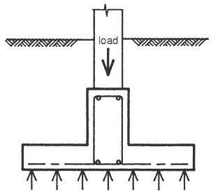
Strip footings and pad bases are used to deliver and spread superstructure loads over a suitable area at foundation  (formation) level. The foundation is required to be stiff enough to distribute the loadings onto the sub-strata in a uniform manner.

1 Strip footings  Strip footings are used under relatively uniform point loads or line loads. The main structural function of the strip is  to disperse the concentration of load sideways into an increased width of sub-strata in order to reduce the bearing stress and....
2 Masonry strips  Masonry strips are rarely used these days, however they can be adopted where good quality sub-strata exists and the raw materials for masonry construction are cheap and abundant. The wall is increased in width by corbelling out the masonry to...

3 Concrete strips – plain and reinforced
4 Concrete trench fill
5 Stone trench fill
6 Rectangular beam strips
7 Inverted T beam strips
8 Pad bases
9 Shallow mass concrete pads
10 Shallow reinforced concrete pads
11 Deep reinforced concrete pads
12 Deep mass concrete pads
13 Balanced pad foundations
14 Rectangular balanced pad foundations
15 Trapezoidal balanced pad foundations
16 Holed balanced pad foundations
17 Cantilever balanced pad foundations