Showing posts with label PILES. Show all posts

Monday, February 18, 2013

Design Example: Piled ground beams with suspended slab

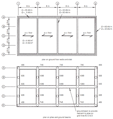
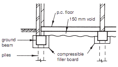
Previously design example  is to be reworked on the assumption that the building is now to be relocated in an area where the  5 m depth of fill is of a much poorer quality, and is con- sidered unsuitable for supporting a floating ground floor slab. The ground floor slab is therefore to be replaced by wide plank precast concrete floors, spanning 8 m parallel to grid lines A–E.

The additional loads due to this suspended floor are shown in Fig. 14.32, and the increased pile loads are indicated.

The increased loads could be catered for by increasing the  number of piles along each load-bearing internal wall  (parallel to grid lines 1–5). In this case however, it has  been decided to maintain the same pile and ground beam layout as in Design Example 3.

Pile capacities
As previously, the pile capacities given in Table 14.9 are derived from previously design Example (Fig. 14.29).

Pile lengths and diameters for Design

Piles of 450 mm diameter will again be used. Comparison with Design Example 3 indicates increases in length of between 0.5 m and 4.6 m.

Check on strength of pile cross-section
A check on the stresses in the pile cross-section, carried out in a similar manner to Design Example 3, indicates that grade C35 concrete is required.

Ground beam size
The ground beams are designed in a similar manner to previously design example, taking due account of the additional loading from the suspended ground floor.

The calculations will be found to indicate that the 600 mm × 625 mm deep ground beams in previously design example will need to be deepened by approximately 200 mm to accommodate this additional loading.

Pile safe working loads for design examples.
Fig. 14.29 Pile safe working loads for design examples.

Piled ground beam and suspended slab design example.
Fig. 14.32 Piled ground beam and suspended slab design example.

Example: Pile cap design.

A pile cap is required to transfer the load from a 400 mm × 400 mm column to four 600 mm diameter piles, as shown in Fig. 14.30.

Pile caps can be designed either by the truss analogy or by bending theory (see BS 8110: Part 1: 3.11.4.1(5)). In this example bending theory will be used.

For a pile cap with closely spaced piles, in addition to bending and bond stress checks, a check should be made on the local shear stress at the face of the column, and a beam shear check for shear across the width of the pile cap. For more widely spaced piles (spacing  > 3  × diameter), a punching shear check should also be carried out.

Local shear check
The ultimate column load is Pu = 6400 kN.

Length of column perimeter is u = 2(400 + 400) = 1600 mm.

The shear stress at the face of the column is


Bending shear check
In accordance with BS 8110: Part 1: 3.11.4.3, shear is checked across a section 20% of the diameter of the pile (i.e. D/5) inside the face of the pile. This is section A–A in Fig. 14.30.

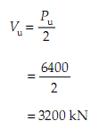
The shear force across this section – ignoring the self-weight of the pile cap, which is small in comparison – is given by


The corresponding shear stress is given by  vu = Vu/bvd, where bv is the breadth of section for reinforcement design.

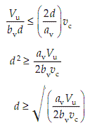
In accordance with BS 8110: Part 1: 3.11.4.4, this must not exceed (2d/av)vc where  av is defined in Fig. 14.30 and  vc is the design concrete shear stress from BS 8110: Part 1: Table 3.8. Thus


For grade C35 concrete, from BS 8110: Part 1: Table 3.8, assuming six T25 bars, the minimum value of  vc is  0.4 N/mm2, giving


Thus, provided the average effective depth exceeds  d = 846 mm (the local shear check), minimum reinforcement  to satisfy bond and bending tension requirements will be adequate in this instance.

The necessary depth for the pile cap is
    h = d + 25(diameter bar) + 75(cover)
       = 846 + 100
       = 946 mm ⇒use h = 950 mm

Pile cap design example.
Fig. 14.30 Pile cap design example.

Friday, February 15, 2013

Design of Foundations at Pile Head.

A general description of ground beams and pile caps is discussed in previously and restraints and cap/beam details are briefly mentioned.

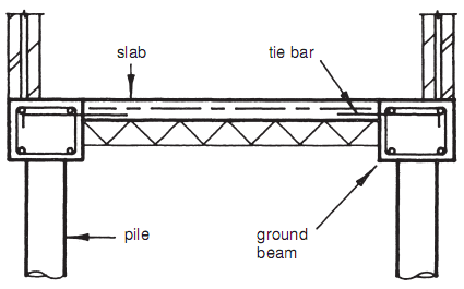
In addition to providing restraint, the ground beam is also used to transfer loads from the superstructure to the pile and can be used with or without pile caps. For example, two alternative layouts are shown in Fig. 14.22 indicating a wide ground beam solution and a narrow beam using pile caps.

Alternative beam/cap layouts.
Fig. 14.22 Alternative beam/cap layouts.

Where the increased width of the beam needed to accommodate the pile diameter, plus the total of all necessary  tolerance, is only slight and where a reduction in beam depth helps to compensate for the additional concrete, a wider beam omitting the pile caps can be more economic.

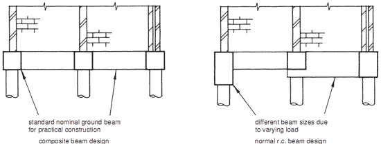
Often the ground beam can be designed compositely with the walls above and by using composite beams a standard nominal size ground beam, dictated mainly by the practicalities for construction, can be used. This has the advantage of standardizing shuttering, reinforcement and excavation, making site construction simple, economic and quicker than the traditional solution. Many different beams designed ignoring the benefit of the contribution from the structure above can severely complicate the foundations (see Fig. 14.23).


 Composite action versus normal design.
Fig. 14.23 Composite action versus normal design.


When considering the use of composite action, consideration must be given to services which may pass through below ground level in these zones. It is often the case that in adopting composite beams the resulting shallow beams can be more easily made to pass over the services. The use of composite action should however be used with caution if there is a requirement to maintain flexibility of future layout. Any modifications involving the introduction of major openings in the walls would invalidate the design assumption that the wall and foundation act together.


A further help in standardizing a smaller and more economic section is that composite action often makes it
possible to precast the beams alongside the excavation and roll them into position, speeding up construction.

For building structures the basic alternative foundations for support on piles generally adopted consists of one or a combination of the following:

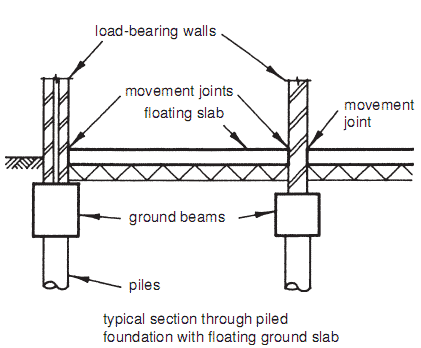
Type 1 Concrete ground beams with or without caps sup- porting the main superstructure load but with a floating ground floor slab between the main wall (see Fig. 14.24).
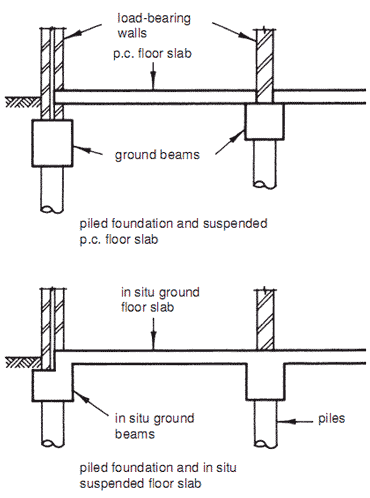
Type 2 Concrete ground beams and suspended in situ or precast concrete floor slabs (see Fig. 14.25).
Type 3 Flat slab construction (see Fig. 14.26).
Type 4 Suspended slab and beam foundations with voids or void formers (see Fig. 14.27).


The economic viability of the pile solutions for the above foundations will differ depending on many variables but, by applying the following basic principles, realistic cost comparisons can be made and piling options exploited:

(1) Minimizing pile numbers relative to pile length/cost and beam length/cost ratio.
(2) Maintaining axial loads on piles and ground beams wherever practical.
(3) Providing pile restraints from other necessary structures wherever practical.
(4) Standardizing on the minimum beam size which can accommodate pile driving tolerances, restraint stresses and pile eccentricity while exploiting any possible composite action.
(5) Minimizing the depth of excavations.
(6) Minimizing the required bending of reinforcement.
(7) Minimizing the shuttering costs by simple standard beam profiles.
(8) Use of simply supported design and simple beam cages wherever possible unless some small cantilever action can greatly reduce the number of piles per unit.
(9) Minimizing the need for pile caps wherever practical by the use of slightly wider beams.

Piles and floating ground slab.
Fig. 14.24 Piles and floating ground slab.


Piles and suspended ground slab.
Fig. 14.25 Piles and suspended ground slab.
Piles and flat slab construction.
Fig. 14.26 Piles and flat slab construction.
Piled suspended slab and beam construction.
Fig. 14.27 Piled suspended slab and beam
construction.

Pile Caps.

1 Introduction
The design of pile caps had at one time become a math-ematician’s delight – and a designer’s nightmare. Highly complex formulae with numerous empirical variants could result in expensive design and construction to save a couple of reinforcing bars. As in all design and construction the aim must be ‘to keep it simple’.

2 The need for pile caps – capping beams
It is frequently not possible to sit a superstructure column direct on to a pile because:

(1) It is practically impossible to drive piles in the exact position and truly vertical. Piles wander in driving and deviate from their true position. A normal specification tolerance for position is ±75 mm and for verticality not more than 1 in 75 for a vertical pile or 1 in 25 for a raking pile. A column sitting directly on a pile with
an eccentricity of 75 mm will exert bending as well as direct stresses in the pile.
(2) A single, heavily loaded column supported by a pile group will need a load spread (pile cap) to transmit the load to all the piles.
(3) A line of piles supporting a load-bearing wall will need a capping beam to allow both for tolerance of pile positioning and load spreading of the piles’ concentrated load to the wall.

3 Size and depth
Pile caps are usually of concrete but can be large slabs of rock or mats of treated timber. This discussion is limited to the more common use of concrete.

To allow for the pile deviation the pile cap should extend 100–150 mm beyond the outer face of the piles. The pile group centroid should ideally coincide with the column’s position (see Fig. 14.16).

Plan on triple pile cap.
Fig. 14.16 Plan on triple pile cap.

The depth must be adequate to resist the high shear force and punching shear and to transmit the vertical load (see Fig. 14.17). The shaded area of the pile cap plan in Fig. 14.17 is the area where the column load is directly transferred to the piles. For such a condition the shear stresses are generally small but bending moments need to be catered for.

 Load transfer from column to piles.
Fig. 14.17 Load transfer from column to piles.

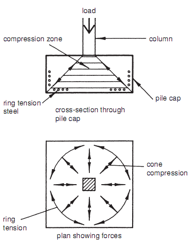
Alternatively, peripheral steel as a ring tension around a cone shaped compression block may be considered to be a suitable equilibrium of forces (see Fig. 14.18), however, full tension laps must be provided for the peripheral steel.

Ring tension pile cap.
Fig. 14.18 Ring tension pile cap.

Single column loads supported on larger pile groups can create significant shear and bending in the cap which will need top and bottom reinforcement as well as shear links (see Fig. 14.19).

Pile cap, typical reinforcement.
Fig. 14.19 Pile cap, typical reinforcement.

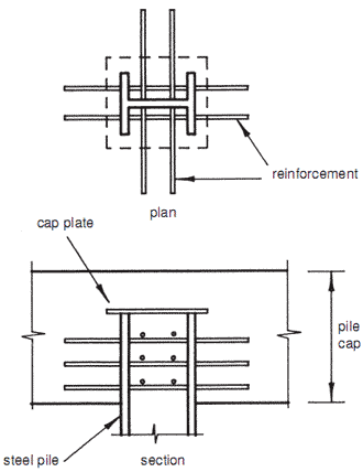
The heads of r.c. piles should be stripped and the exposed reinforcement bonded into the pile cap for the necessary bond length. Pile caps to steel piles can be reduced in depth if punching shear is reduced by capping and/or reinforcing the head of the pile, as shown in Fig. 14.20.

Reinforced pile head.
Fig. 14.20 Reinforced pile head.

Piles for continuous capping beams supporting load-bearing walls can be alternately staggered to compensate for the eccentricity of loading due to the 75 mm out-of-line tolerance (see Fig. 14.21).

 Continuous capping beam.
Fig. 14.21 Continuous capping beam.

Pile Groups.

It is sometimes necessary to drive a group of piles to support heavy loadings and it is important to notice two effects:

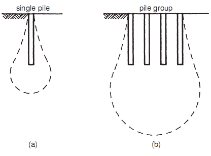
(1) The pressure bulb of the group affects deeper layers of soils than a single pile of the same depth (see Fig. 14.13) in a similar manner to a wide foundation.
(2) The load-bearing capacity of a group is not necessarily the product of the capacity of the single pile times the number of piles. There can be a pressure ‘overlap’ (see Fig. 14.14) and the capacity of the group could decrease as the difference between a pad and strip foundation.

A single pile, in driving, displaces soil which can result in heave at ground level and a group can cause greater heave and displacement; this fact should be checked and considered. Driving a single pile, too, in loose sand and fills will compact the soil around the pile to a diameter of approximately 5.5 times the pile diameter and make it denser. If a group of piles is driven it could create such a compact block of soil as to prevent driving of all the piles in the group. The central piles should be driven first and then, working out to the perimeter of the group, the remaining piles should be driven.

Section through pile pressure bulbs.
Fig. 14.13 Section through pile pressure bulbs.

Plan on pile pressure bulbs.
Fig. 14.14 Plan on pile pressure bulbs.

Spacing of piles within a group

Approximate values for centre-to-centre spacing are as follows:
 

(1) Friction piles – not less than the perimeter of the pile.
(2) End-bearing piles – not less than twice the diameter of the pile.

(3) Screw piles – not less than 1.5 times the diameter of the blades.
(4) Piles with enlarged bases – at least one pile diameter between enlarged bases.
 

These values are affected by the soil conditions, the group behaviour of the piles, the possible heave and compaction, and the need to provide sufficient space to install the piles to the designed penetration without damage to the pile or group.

Piles - Factor of safety.

BS 8004 recommends a factor of safety of between 2 and 3 for a single pile. The factor of safety is not a fixed constant and depends on the allowable settlement of the pile which is dependent on the pile’s surface and cross-sectional area, the compressibility of the soil, and the reliability of the ground conditions. The factor should be increased when:

(1) The soil is variable, little is known of its behaviour or its resistance is likely to deteriorate with time.
(2) Small amounts of differential settlement are critical.
(3) The piles are installed in groups.

The factor may be decreased when:

(1) As a result of extensive loading tests, the resistance can be confidently predicted.
(2) As a result of extensive local experience, the soil properties are fully known.

A common factor of safety taken in design is 2.5. A properly designed single 500 mm diameter pile driven into noncohesive soil is unlikely to settle more than about 15 mm.

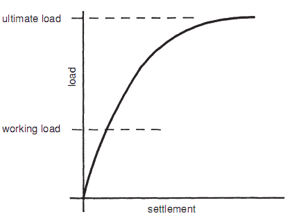
In a load test the settlement is noted for increasing increments of load and a settlement/load graph is plotted. The graph resembles that of the stress/strain graph for many structural materials (see Fig. 14.12). Up to working load there tends to be practically full recovery of settlement on removal of load but beyond that loading there is likely to be a permanent set (as in steel loaded beyond the elastic limit) and at ultimate load there is likely to be no recovery at all.

Load/settlement graph.
Fig. 14.12 Load/settlement graph.

Wednesday, February 13, 2013

Choice of Pile.

Having found a satisfactory pile and a reliable and cooperative piling contractor for a particular site and conditions, there is a temptation for a busy designer, with  inadequate time to investigate the wide choice of piles and systems, to use the same piling contractor for all future  projects. This understandable reaction does not make for cost effectiveness nor structural efficiency. A guide to the choices available is given below:

(1) The piling system must provide a safe foundation with an adequate factor of safety against failure of the foundation on supporting soil.

(2) The total settlement and differential settlement must be limited to that which the structure can tolerate.

(3) The pile should be the right type of pile for the ground conditions and structure.

(4) The driving of the piles and the load they impose on the soil must not damage neighbouring structures.

(5) The piles must be economic and durable, and where speed of construction is important, quick to place.

1 Ground conditions and structure

(1) When invited to tender for the contract the piling contractors should be provided with a soil report, the position and magnitude of structural loads and the location of the structure together with information on adjoining properties. They should also be asked to visit the site to inspect the access for piling plant movements.

(2) Driven and cast-in-place piles, where the shell is left in, are used on sites over water (jetties, piers, etc.), on sites known to contain large voids, and on sites subject to high water pressure. Driven piles should not be chosen where the ground is likely to contain large boulders but they are one of the best piles for loose-to-compact wet sands and gravels.

These types of piles are frequently the cheapest to use on building sites with light-to-moderate pile loadings
and where the charges for moving onto site are spread over a large number of piles.

(3) Bored piles are frequently the lowest cost piles when piling into firm clays or sandstone and when vibration and ground heave would cause problems to existing adjacent buildings.
(4) Jacked piles need something to jack against and tend  to be expensive. Their main use is therefore in underpinning when they can prove to be cost-effective.
(5) Steel H piles are often chosen when long length  piles with deep penetration into sands and gravels are required.

2 Durability
The ground conditions can affect the choice and method of protection of piling material. Sulfates and acids will attack poor-quality concrete, some acids will cause problems with steel piles and alternate wetting and drying can cause timbers to rot.

3 Cost
Piles are, or should be, chosen as the economic and safe alternative to strip and raft foundations but there is more to cost analysis than comparing the cost per metre run of piles; there are on-costs. In comparing piling contractors’ estimates it can be unwise to accept the lowest cost per metre run.

Examination of extra over-costs for such items as extending lengths of piles, conducting check loading tests, etc. is  prudent. The designer should examine the piling contractor’s resources available to complete the project on time, the length of notice required to start work and the contractor’s experience in piling on similar sites. The  contractor’s reputation should be investigated and proof obtained of adequate insurance to indemnify building owners for any claims or damage to adjoining buildings  or failure of piles due to design and construction faults.

To the cost of the piles must be added the cost of excavation for constructing pile caps and any necessary tie beams. This increases the cost of construction supervision and design.

Decisions must be taken early so that design, detailing, construction and planning can be completed well in advance  of starting the contract. Too often the time is restricted by delays in site investigations, change of design brief, recent changes in contractors’ prices, etc.

Methods of Piling.

There is a wide variety of methods used for piling and every piling contractor has a number of variations for  their system – improvements in method and equipment continues. The main classes only are discussed below.

1 Driven piles
This method is used for piles of timber, precast concrete, prestressed concrete and the various types of steel piles.

The pile is hammered into the ground by pile-driving plant shown in outline in Fig. 14.10 (a). Methods of protecting the head of the pile from shattering are shown in Fig. 14.10 (b).


Driven piling.
Fig. 14.10 Driven piling.

Driven piles are classified as displacement piles and, where the soil can enter during driving, as small displacement piles (e.g. open ended tubular or other hollow sections often in steel).

2 Driven cast-in-place piles
A closed ended hollow steel or concrete casing is driven into the ground and then filled with fresh concrete. The casing may be left in position to form part of the whole  pile or withdrawn for reuse as the cast concrete is placed.

The cast concrete is rammed into position by a hammer as the casing is withdrawn ensuring firm contact with the soil and compaction of the concrete. Care must be taken to see that the cast concrete is not over-rammed or the casing withdrawn too quickly. There is a danger that as the liner
tube is withdrawn it can lift up the upper portion of in situ concrete leaving a void or necking in the upper portions of the pile. This can be avoided by good quality control of the concrete and slow withdrawal of the casing.

Driven cast in situ piles can prove to be economic for sands, loose gravels, soft silts and clays particularly when large numbers of piles are required. For small numbers of piles the on-site costs can however prove to be expensive.

3 Bored cast-in-place piles
The hole for the pile shaft is formed by drilling or augering and the toe of the hole can he enlarged by under-reaming in stiff clays to provide greater end-bearing capacity for the pile. The method tends to be restricted to clayey soils and, as with the driven cast-in-place pile, care must be exercised to prevent necking of the cast concrete. If they are used in loose sand or silt the inflow of soil into the bore must be  prevented. They can be installed in very long lengths and be of large diameter.

The relatively small on-site cost of bored piles means that smaller sites can be more economically piled than they can using a driven piling system. The bored pile is not usually economic in granular soils where loosening and disturbance of surrounding ground can cause excessive removal of soil and induce settlement in the surrounding area. During piling operations the hole can be lined with a casing which can be driven ahead of the bore to overcome difficulties caused by groundwater and soft sub-soil but sometimes difficulties of withdrawing the casing after casting can prove expensive.

4 Screw piles
Screw piles of steel or concrete cylinders with helical blades attached are screwed into the ground by rotating the blades. Their best application is in deep stratum of soft  alluvial soils underlain by firm strata. Due to the large diameter of the blades the piles have increased resistance  to uplift forces. Screw piles can be removed after use in  temporary works.

5 Jacked piles
Jacked piles are used where headroom for the pile and pile driver are limited as in underpinning within an existing building. The pile is jacked in short sections using the existing superstructure as a reaction frame.

6 Continuous flight auger piles
The flight auger pile system uses a hollow stem auger mounted on a mobile rig. The auger is drilled into the
ground with very little vibration and spoil removal. When the required depth has been reached (see Fig. 14.11), concrete or grout is injected through the auger shaft. Usually the concrete or grout mixing plant and the pumping equipment are located nearby but can, if such areas are sensitive, be located well away from such positions. Pile lengths of up to 25 m can generally be achieved with pile diameters from 300 mm to 600 mm. Piles can be raked up to an angle of 1 in 6 from vertical. The system is suitable for use in most virgin soils and fine granular fills and rigs can operate in areas with restricted headroom.

Flight auger pile.
Fig. 14.11 Flight auger pile.

7 Mini or pin piles
There are a number of mini or pin piles on the market. The systems range from water- or air-flushed rotary percussion augers to small-diameter driven steel cased piles which are driven to a set.

The pile diameters generally vary between 90 mm and  220 mm and can be used in most soils and with restricted access/limited headroom. Where necessary, noise and vibration can be kept to a minimum and piles can be driven within a few hundred millimetres of adjacent properties.

In underpinning they can be used to penetrate existing  concrete or masonry foundations, and can be bonded into the existing elements or form part of a new support system in conjunction with cast-in-situ ‘needle’ beams.

Slenderness of such small-diameter piles must however be taken into account and the need for good quality control particularly with regard to filling such small bores with concrete.

The piles are not generally suitable in mining areas where surface movements and lateral strains may be expected to distort or shear the piles.

Monday, February 11, 2013

Steel Piles.

Though most piling is carried out using some form of  concrete there are situations where steel piles should be considered. There is considerable experience of the use  of sheet piling in civil engineering which can be applied  to piles for structures. The piles are generally a standard  H section (see Table 14.1) or, for longer or more heavily loaded sections, tubular box section piles are used (see Table 14.2). In some cases they can form a structurally efficient and cost-effective solution. The advantages of steel piles compared with concrete are:

(i) They have a lighter weight for a required load-bearing capacity.
(ii) They can be used in longer lengths and extending them by butt welding is relatively simple. Similarly excess length is easily cut off.
(iii) They are more resistant to handling and driving stresses.
(iv) They can have good resistance to lateral forces, bending stresses and buckling.
(v) They are particularly useful for marine structures (piers, jetties, etc.) above water where the piles may be subjected to impact forces, ships docking, etc.

The disadvantages of steel piles are:

(i) There is a need for corrosion-protection.
(ii) The pile cost per metre run can be relatively high.
(iii) There are fewer piling sub-contractors competent to carry out the work.
(iv) There is a tendency for H sections to bend about the weak axis when being driven – the resulting curved pile has a lower bearing capacity.

The use of stones or large gravel in piling is now a well-developed technique. The authors have been involved  in extensive use of this form of piling for many years.

The method is used mainly as a geotechnical process to  consolidate and compact soils and/or to improve their drainage. The technique is discussed in detail previously and reference should be made to that chapter for further information.

Table 14.1 Steel H piles – dimensions and properties
Steel H piles – dimensions and properties


Table 14.2 CAZ box piles – dimensions and properties
CAZ box piles – dimensions and properties

Concrete Piles.

Concrete piles are the most widely used in the developed countries and may be cast in situ, precast, reinforced and prestressed.

(a) Precast
This type is commonly used where:

(i) The length required can be realistically predicted.
(ii) Lateral pressure from a stratum within the soil profile is sufficient to squeeze (neck) a cast-in-situ pile.
(iii) Where there are large voids in sections of the soil which would possibly have to be filled with an excessive amount of in situ concrete or could cause loss of support for wet concrete prior to setting.
(iv) For structures such as piers and jetties above water level on coastal, estuary and river sites.

Though precast piles can be manufactured on site it is  more common to have them designed, manufactured and installed by specialist subcontractors.

There are disadvantages in the use of precast concrete piles as follows:

(i) It is not easy to extend their length.
(ii) They are liable to fracture when driven into such obstacles as large boulders in boulder clay and the damage can remain out of sight.
(iii) Obstructions can cause the pile to deflect from the true vertical line.
(iv) There is an economic limit, restricted by buckling, of the unrestrained length of the pile.
(v) Noise and vibration caused by driving can cause nuisance and damage.
(vi) There can be large wastage and health and safety risks to the workforce caused by noise and vibration due to the need to cut off the projecting length after driving.
(vii) The accuracy of the estimated length is only proved on site when short piles can be difficult to extend and long piles can prove to be expensive and wasteful.
(viii) The relatively large rig required for driving often needs extensive hard-standings to provide a suitable surface for pile driving.

The advantages of precast concrete piles are:

(i) It is easier to supervise the initial quality of construction in precast than in situ.
(ii) The pile is not driven until the concrete is matured.
(iii) Stresses due to driving are usually higher than those due to foundation loading so that manufacturing faults are more easily discovered and, in effect, the  pile is preload tested (provided the defects can be detected).

The reinforcement, while adding to the load-bearing capa- city, is mainly designed to cope with handling, transporting and driving stresses.

(b) Cast in situ
There is an ever increasing variety of cast in situ piles offered by specialist piling subcontractors. The piles are
usually circular in cross-section and are regarded as small- diameter piles when their diameters are from 250–600 mm and larger-diameter piles when their diameters exceed  600 mm; large-diameter piles are now possible with dia- meters up to 3.0 m.

The advantages of cast in situ piles are:

(i) They can be constructed immediately, thus cutting out the time required for casting, maturing and delivering of precast piles.
(ii) There is no need to cut off or extend excessive lengths of the piles as they can be cast in situ to the required level.
(iii) They can be cast to longer lengths than is practical with precast piles.
(iv) Most obstructions can be hammered and broken through by the pile-driving techniques.
(v) The placing can cause less noise vibration and other disturbance compared to driving precast piles.
(vi) Soil taken from boring can be inspected and compared with the anticipated conditions.

The disadvantages of cast in situ piles are:

(i) It can be difficult to place and ensure positioning of any necessary reinforcement.
(ii) Concrete quality control is more difficult.
(iii) There is a danger of necking from lateral earth pressure.
(iv) Young concrete is susceptible to attack from some soil chemicals before it has set and hardened.

(c) Prestressed
Prestressed concrete in superstructure design is made of higher strength concrete, requires smaller cross-sectional area and can be made impact-resistant. The same results apply to prestressed piles relative to comparison with pre- cast reinforced piles. Their advantages compared to precast reinforced are:

(i) Handling stresses can be resisted by a smaller cross- section which can result in a more economical pile.
(ii) It is easier with the smaller section to achieve longer penetration into load-bearing gravels.
(iii) Tensile stresses that are generated up from the toe of the pile after the hammer blow can be compensated for by prestress.
(iv) The reduction of tensile cracking of the concrete can lead to greater durability.

The disadvantages of prestressed piles are:

(i) The smaller section provides less end bearing and total peripheral skin friction.
(ii) Deeper penetration into end-bearing strata (gravel, compact sand, etc.) may be necessary.
(iii) It is more difficult to extend the length of a precast driven pile.
(iv) As in prestressed concrete superstructure elements, stricter quality control in manufacture is necessary.

Timber Piles.

The oldest material used for piles is timber and it is still  in use, particularly in developing countries, today. It has proved surprisingly durable and provided care is given to the detail and treatment of the toe and head of the pile and the durability conditions it should still be used where it is economical. The toe can be subject to splintering during driving and should be tapered to a blunted point and,  if necessary, encased in steel. The head of the pile during driving may also need protection from splintering and this is usually provided by placing a driving cap or helmet over the head of the pile.

Where the top of the pile is below the lowest water level and is in permanently wet conditions, experience shows that there are few durability problems. However, when the level of the top of the pile or any part of it is in the area of a fluctuating water-table and is therefore subjected to alternate wetting and drying, this section of the pile should be treated with preservatives and water repellents and even then may still have a limited life.

If the length of the pile is found on site to be too long there is little problem in cutting off the excess length but there is a problem if the pile is found to be too short. Extending the pile involves splicing on an added length and any metal connections must be corrosion-resistant.

The choice of timber is not restricted to dense timbers such as greenheart or oak, except in conditions where the pile is subject to alternate wetting and drying such as in piles  supporting jetties in tidal conditions. In numerous structural surveys of Victorian buildings the authors’ practice has discovered, in good condition below the water-table level, timbers such as birch, larch, pine, etc.

Thursday, February 7, 2013

Piles - Typical Applications.

Typical applications of piling are:

(1) Where soil of low bearing capacity of significant depth is underlain by strong strata.

Piling which transfers the foundation load to the strong strata is frequently a more economic solution than alternative foundations (see Fig. 14.1).


Stiff strata at depth.
Fig. 14.1 Stiff strata at depth.

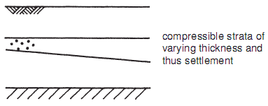
(2) Where the surface strata is susceptible to unacceptable settlement, and is underlain by stiff material (see Fig. 14.2).

Compressible strata.
Fig. 14.2 Compressible strata.

On a low-cost site the authors’ practice has installed 18 m long in situ concrete piles to support two-storey domestic housing. The increased cost of the piles was more than compensated for by the low cost of the site.

(3) Where surface foundation would impose unacceptable increase in bearing pressure, or surcharge, on
existing foundations (see Fig. 14.3).


 Load transfer below existing foundation.
Fig. 14.3 Load transfer below existing foundation.

(4) Where the foundation is subject to lateral loads which can be more economically resisted by raking piles (see Fig. 14.4).


Lateral resistance.
Fig. 14.4 Lateral resistance.

(5) Where variations in the compressibility of the soil would lead to excessive differential settlement of surface foundations (see Fig. 14.5). The leaning tower of Pisa is a classic example of differential settlement.


Variable compressibility.
Fig. 14.5 Variable compressibility.

(6) Where excavation to firm strata would prove ex- pensive and difficult, e.g. soft waterlogged alluvial deposits. On one important contract, near the coast in North Wales, it was found that the proposed structure
was sited over a glaciated channel filled to a depth  of 15 m with a soft, highly saturated silt which was impossible to dewater. Excavation and foundation construction would have been difficult and expensive.

(7) Where, on sloping sites, it is necessary to transfer the additional load to a level below the possible slip circle (see Fig. 14.6).


Load transfer below critical slip circle.
Fig. 14.6 Load transfer below critical slip circle.

(8) Where anchoring of a flotation foundation by tying down or tension pile is necessary (see Fig. 14.7).


Anchorage against flotation.
Fig. 14.7 Anchorage against flotation.

(9) Where heave and swelling of clay could exert excessive forces and movements on surface spread foundations.

(10) Whenever piling is a more economic solution. In the past few decades there have been advances in piling manufacture and construction which have considerably reduced the cost of piling. Piling is no longer a last resort but can be considered as an economic alternative in foundation design.

Piles should be used with caution, if at all, where the ground is subject to significant lateral movement, e.g. in areas affected by mining, as such movements can shear off the piles leaving the structure unsupported.

Monday, January 7, 2013

Pile Caps and Ground Beams.

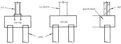
Many piled foundations consist of a number of relatively small-diameter piles and they require a practical driving tolerance. Pile caps or capping beams are required to accommodate this tolerance and to pick up varying widths of super-structure elements. In some situations, where large-diameter piles are used, pile caps or beams are unnecessary.

However, this is the minority case. The caps consist of  concrete pads or beams constructed at the head of the piles to provide the connection between the pile and super-structure (see Fig. 9.44).

In addition to transferring the vertical load from the super-structure to the foundation, there is often a need to provide lateral restraint to the tops of the piles, particularly where less than three piles are provided. For small low-rise developments (single- or two-storey construction) the amount  of restraint required to the tops of the piles can be provided by the use of the ground floor slab or a lightweight raft foundation (see Fig. 9.45).

Fig. 9.44 Pile caps.


Fig. 9.45 Pile cap/beam restraint.

Anchor Piles - Description.

Anchor piles are piles used to resist uplift or inclined tensile
forces in the surrounding ground. They are used as:

(1) Reaction piles for pile testing.
(2) Piles to resist uplift forces from flotation.
(3) Anchorage to react to cantilevered foundations, etc.(see Fig. 9.40).

The piles are designed as tension piles transferring their load to the ground by friction, by under-reaming or by bonding into unfractured rock (see Fig. 9.41). It is most important that allowance be made, when anchoring into rock, for the possible damage and shattering of the rock or pile surface during driving.

It is also important to give special consideration to the  use of piles as anchor piles for testing if they are to be  incorporated as working piles in the final scheme.

Fig. 9.40 Anchor piles.


Fig. 9.41 Tension piles.

Steel Piles - Description.

Steel piles, like timber, are driven by percussion means and have a variety of suitable cross-sections. In addition to the common sheet piles, the three main types are H sections, box piles and tube piles. Typical sections are shown in Fig. 9.39.

The main use of steel piles is for temporary works, retaining walls and marine structures. The problem of corrosion of the steel can be overcome by suitable protection. However, account should be taken of the abrasion during driving on the final performance of such protection/coatings. In addition to coating, increased metal thickness and cathodic protection may be appropriate for particular locations and conditions. Detailed information on these aspects along with detailed information on steel piles and piling is outside the scope of this book due to their limited use in structural foundations.

Fig. 9.39 Typical steel pile cross-sections.

Monday, December 31, 2012

Augered Piles - Characteristics.

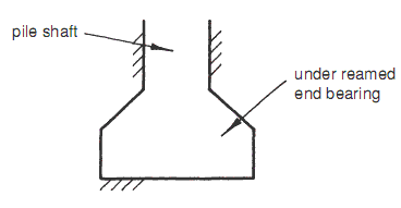
The augered pile is usually constructed by screwing a rotary auger into the ground. The material is either augered out in a similar manner to that of a carpenter’s bit and the open hole filled with concrete or alternatively an auger with a hole down its centre is used and a cement grout injected under pressure down the hole during withdrawal of the auger. Early problems experienced with voids left by rapid withdrawal of the auger before properly filling the pile shaft have now been overcome by the use of computer controlled rigs which monitor concrete pressure and give a continuous readout for quality control purposes. Augers can be used to drill large-diameter holes in a wide range of soils, the range having been extended by the use of  bentonite slurry to assist the support of the sides of the hole in soft silts and clays. In addition, the large-diameter auger can be used with under-reaming tools to enlarge the end bearing base of the pile (see Fig. 9.37).

Probably one of the most successful auger methods is the use of the hollow tube auger in soft silt, etc., where
water and squeezing of soft silts in the surrounding ground can cause necking problems for many other systems, i.e. squeezing in of the pile shaft due to side pressure. The use of the hollow auger and injected sand cement grout can produce good-quality piles in these soft and difficult conditions at competitive prices, particularly where large numbers of piles are involved. For small numbers of piles the on-site cost of the rig and grouting plant can prove to be prohibitively expensive.

Fig. 9.37 Under-reamed augered pile.

Bored Piles - Characteristics.

The bored pile is usually formed by using a simple cable percussion rig. The soil is removed by shell and auger and the hole filled with in situ reinforced concrete as required (see Fig. 9.36).

For filled sites or soft clay sites overlying stiff clay or rock, small to medium bored piles often prove to be economic.

The relatively small on-site cost of bored piles means that smaller sites can be piled more economically than they can using a driven piling system. The bored pile is not usually economic in granular soils where removal and disturbance of surrounding ground can cause excessive removal of soil and induce settlement in the surrounding area. During  piling operations the hole can be lined with a casing which can be driven ahead of the bore to overcome difficulties caused by groundwater and soft sub-soil but sometimes difficulties of withdrawing the casing after casting can prove expensive.

Fig. 9.36 Bored pile.

Driven Cast In Situ Piles.

Driven cast in situ piles use steel, or precast concrete, driving tubes which are filled with in situ concrete after driving.

Variations in pile lengths can be more easily accommodated using segmental liners. The piles can be cast accurately to the required length and the driving or liner tube can be driven in short lengths. In some cases the tube is left in position permanently and in other cases the tube is withdrawn and used to tamp the concrete by lifting and dropping the liner tube. In other situations the tube is with-drawn and vibrated as the concrete is poured and additional compaction achieved by impact to the surface of the wet concrete. Driven piles can therefore have a smooth or irregular side surface depending on the method of driving and this results in differing friction and mechanical keying to the surrounding soil which varies depending on the pile type and sub-soil conditions. Again large rigs are required for driving cast in situ piles and hardstanding requirements can prove expensive.

In piling systems where the liner tubes are withdrawn there is a danger that the tube can lift the upper portion of in situ concrete leaving a void a short distance below the surface or squeezing during withdrawal can cause necking. This can happen where the mix is not carefully controlled or where the liner tube is not withdrawn at a steady slow rate.

Driven cast in situ piles, however, can prove to be economic for sands, gravels, soft silts and clays, particularly when large numbers of piles are required. For small numbers of piles the on-site cost can prove expensive. Driven precast piles and driven cast in situ piles can prove particularly suitable where groundwater or soft inclusions occur in the sub-strata.

Driven Precast Piles.

Driven precast piles can be used in areas where the soils, through which the pile is to be driven, are relatively soft and unobstructed and where the length of pile required can be determined to a reasonable accuracy. The piles can be cast to any suitable cross-section, i.e. square, rectangular, circular, hexagonal, etc. The shape and protection to the point of the pile is determined from the end bearing requirements and driving conditions. The pile head and the reinforcement are designed to take account of the pile-driving impact loads. Some disadvantages of this method of piling are that the pile can be damaged in a location out of sight during driving and the pile can be displaced if it meets an obstruction such as a boulder in the ground. In addition the accuracy of the estimated length is only proved on site and short piles can be difficult to extend and long piles can prove to be expensive and wasteful. A further disadvantage is the relatively large rig required for driving and the need for hardstandings that are often required to provide a suitable surface for the pile-driving plant.
Concrete Piles - Uses.

Concrete piles are generally used to transfer loads through an unsuitable bearing material to a deeper load-bearing strata. This is achieved either by skin friction and end bearing or end bearing alone (see Fig. 9.34).

There are many different types and systems of piles,  however the main types are:

(1) Driven precast piles.
(2) Driven cast in situ piles.
(3) Bored piles.
(4) Augered piles.

These piles can also be divided into either displacement or replacement methods dependent on the system of driving, i.e. either removal of material, termed  replacement, or  wedging apart of material, termed  displacement. Typical examples of these types are shown in Fig. 9.35.

Fig. 9.34 Typical concrete pile.


Fig. 9.35 Concrete pile types.