Showing posts with label DRILLED SHAFTS. Show all posts

Friday, November 23, 2012

Load tests - Drilled Shafts.

The only positive way to prove the integrity  of a suspected drilled shaft is to perform a load test.  Drilled shafts are often constructed in relatively large sizes  and load tests are often not economically feasible.

Replacing  a suspected drilled shaft is often more economical than performing the load test.

(1)  Application. Shall be performed for drilled shafts when economically feasible such as for large projects.  Results of load tests can be used to reduce the FS from 3 to 2 and can increase  the economy of the foundation when performed during design.

(2)  Preload.  An alternative to load tests is to construct the superstructure and to preload the structure to determine the  integrity of the foundation.  This test must be halted immediately  if one or more drilled shafts show more settlement than is anticipated.

Nondestructive Tests - Drilled Shafts.

b.   Nondestructive tests.  Routine inspection with nondestructive  tests (NDT) using wave propagation shall be performed  to check the quality of the installed drilled shafts.

Additional special tests as indicated in the following paragraphs are performed if defects are suspected in some drilled shafts.

Routine tests performed as part of the inspection procedure are typically inexpensive and require little time.  Special tests to determine  defects, however, are often time consuming, expensive, and performed only for unusual situations.

(1)  Routine inspection tests.  The most common routine NDT  is  to externally vibrate the drilled shaft by applying a sudden load as from a hammer or heavy weight dropped from a specified height.  Signals from the wave are recorded by transducers and accelerometers installed near the top of the shaft or embedded in the concrete at some location in the length of the shaft.  Access tubes may  also be installed in the shaft for down-hole instrumentation to investigate the concrete between access tubes.  Refer to FHWA-HI-88-042

(a)   The PDA procedure as discussed for driven piles may also be used for drilled shafts, even though it cannot be considered  a routine test for NDT.  The force-time and velocity-time  traces ofo the vibration recorded on the oscilloscope caused by a dynamic load can be interpreted by an experienced technician to determine discontinuities and their location in the concrete.

(b) The wave pattern of large displacements caused by dropping  sufficiently large weights from some specified height  can be analyzed by the PDA procedure and CAPWAPC  method to determine the ultimate bearing capacity and load-displacement behavior.

(c)  Vibration from a hammer blow measured with embedded  velocity transducers (geophones) can confirm
any  possible irregularities in the signal and shaft defects.

The  transducers are inexpensive and any number can be readily installed and sealed in epoxy-coated aluminum cases on the reinforcing cage with no delay in construction.  The embedded  receivers provide a much reduced noise level that  can eliminate much of the requirement for signal processing.

(d)   Forced vibrations induced by an electrodynamic vibrator  over a load cell can be monitored by four accelerometers installed near the shaft head (Preiss, Weber, and Caiserman 1978).  The curve of v0  / F0  , where v0  is the o o o maximum velocity at the head of the drilled shaft and F0  is o the applied force, is plotted.  An experienced operator can determine the quality of the concrete such as discontinuities and  major faults if the length of the shaft is known. Information below an enlarged section cannot be obtained.

(2)  Access tubes and down-hole instruments.  Metal or plastic tubes can be cast longitudinally into a drilled shaft that  has been preselected for special tests.  These tubes usually extend full length, are plugged at the lower end to keep  out concrete, and are fastened to the rebar cage.

Various instruments can be lowered down the access tubes to generate and receive signals to investigate the quality of the concrete.

(a)  A probe that delivers a sonic signal can be inserted down a tube and signal receivers inserted in other tubes.

One tube can check the quality of concrete around the tube or multiple tubes can check the concrete between the tubes.

(b)   An acoustic transmitter can be inserted in a fluid-filled tube installed in a drilled shaft and a receiver inserted to the same depth in an adjacent tube.  This test can also be performed on a drilled shaft with only a single tube using a probe that contains the receiver separated by an acoustic isolator.  A single tube can be used to check the quality of concrete around the tube.

(c)  A gamma-ray source can be lowered down one tube and a detector lowered down to the same depth in another tube  to check the density of concrete between the source and detector.  A change in the signal as the instruments are lowered indicates a void or imperfection in the concrete.

(3)  Drilling and coring.  Drilled shafts that are suspected  of having a defect may be drilled or cored to check the quality of the concrete.  Drilling is to make a hole into the shaft without obtaining a sample.  Coring is boring and removal of concrete sample.  Drilling and coring can  indicate  the nature of the concrete, but the volume of concrete that is checked is relatively small and drilling or coring  is time consuming, costly, and sometimes misleading.  The direction of drilling is difficult to control, and the hole may run out the side of the shaft or might run into  the reinforcement steel.  Experienced personnel and proper equipment are also required to ensure that drilling is done correctly and on time.

(a)   Drilling is much faster than coring, but less information is gained.  The drilling rate can infer the quality
of  concrete and determine if any soil is in the shaft.  A caliper can measure the diameter of the hole and determine any anomalies.

(b)  Coring can determine the amount of concrete recovery and the concrete samples examined for inclusions
of  soil or slurry.  Compression tests can be performed to determine the strength of the concrete samples. 

The cores can  also be checked to determine the concrete to soil  contact at the bottom of the shaft.


(c)  Holes bored in concrete can be checked with  a television  camera if such an instrument is available.  A portion of a borehole can also be packed to perform a fluid pressure  test to check for leaks that could be caused by defects.

(d)  Defects of large size such as caused by the collapse of the excavation prior to concrete placement or if concrete is absent in some portion of the shaft can be detected by drilling or coring.  Defects can be missed such as when the sides of a rock socket are smeared with remolded and weak material.  Coring can also detect defects that appear to be severe  but are actually minor.  For example, coring can indicate weak concrete or poor material, or poor contact with the end bearing soil or rock in the region of the core, but  the remaining shaft could be sound and adequately supported by the soil.

Drilled Shafts - Performance Control.

Continuous monitoring is essential to ensure that the boreholes are properly prepared to minimize loss of soil friction and end-bearing capacity and that the concrete mix is placed to achieve a continuous adequate shaft.  Complete details of a drilled shaft const ruction control and an example of quality control forms  may be found in FHWA-HI-88-042, “Drilled Shafts: Construction Procedures and Design Methods” and ADSC
(1989)  report, “Drilled Shaft Inspector’s Manual.” Construction and quality control include the following:

(1)  Borehole excavation.  Soil classification provided by all available boring logs in the construction area should be correlated with the visual description of soil or rock removed from  the excavation.  Any observed groundwater levels should also be recorded.  Characteristics to be observed and determined  include determined include location of the various strata, location and nature of the bearing stratum, and any seepage.  The observer should also determine if the soil profile is substantially different from the one assumed for the design based on knowledge of the plans, specifications, and previous geotechnical analysis.  The design engineer should be at the construction site during boring of the first holes to verify assumptions regarding the subsurface soil profile and periodically  thereafter to check on requirements for any design modifications.

(a)  Excavation details such as changes in the advance rate  of the boring tool and changes in the soil cutting,
groundwater  observations, and bottom heave should be recorded.  These details can be used to modify excavation procedure and improve efficiency in the event of problems as well as to provide a complete record for later reference.

Other important data include type of excavation (e.g., dry, cased, or slurry), time of initiation and completion of the boring, estimates of location of changes in the soil strata, and description of each soil stratum. 

Determine any evidence of pervious  lenses and groundwater, problems encountered during excavating (e.g., caving, squeezing, seepage, cobbles, or  boulders), and the location of the bearing stratum.  A small diameter test boring from the excavation bottom can be made and an undisturbed sample recovered to test the bearing soil.

(b)  The excavation should be checked for proper length, diameter, and underream dimensions.  Any lateral deviations from the plan location and unintentional inclination or batter should be noted on the report and checked to be within the required tolerance.  Provided that all safety precautions have been satisified, the underream diameter can be checked by placing the underream tool at the bottom of the excavation and comparing the travel of the kelly when the underreamer is extended to the travel when it is retracted in the barrel of the underream tool.  Electronic calipers may be used if the excavation was made with slurry or the hole cannot be entered for visual inspection.  Extreme safety precautions must be taken if an inspector enters an excavation to ensure no  fall-in of material, and he should be provided with adequate  air supply, communications and lifeline, and hoisting equipment.  In the event of entry, a liner or casing should be in place to protect against fall-in.  Fresh air may be pumped through hoses extending to the bottom.  Minimum diameter of casing for personal inspection is 2 feet.  An alternative to downhole inspection is to utilize ADSC drilled shaft inspectors manuals.

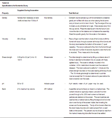
(c)   Slurry used during excavation should be tested for compliance with mix specifications after the slurry is mixed and  prior to placing in the excavation.  These tests are described  in Table 6-3 and should be performed by the Government and reported to construction management and the designer.


(d)  The bottom of the excavation should be checked before placement of the reinforcement cage and concrete to ensure that all loose soil is removed, water has not collected on the bottom of open boreholes, and the soil is in the correct bearing stratum.  Depth of water in an open borehole should be less than 2 inches.  Casing should be clean, smooth, and undeformed.

(2)  Placement of reinforcement.  The reinforcement cage should be assembled prior to placement in the excavation with the specified grade, size, and number of bars.  The cage  should be supported with the specified horizontal stirrups or spirals either tied or welded in place as required to hold bars in  place and prevent misalignment during concrete placement and removal of casing.  The minimum spacing between bars should be checked to ensure compliance with specifications  for adequate flow of concrete through the
cage.   The cage should be checked for placement in the specified  position and adequately restrained from lateral movement during concrete placement.


(3)  Concrete placement.  The properties of the concrete mix and placement method must be closely monitored to avoid defects in the shaft.  A record of the type of cement, mix proportions, admixtures, quantities, and time loaded on the truck should be provided on the delivery ticket issued by the concrete supplier.  The lapse of time since excavation of the borehole and method of concrete placement, including details of the tremie used to place the concrete, should be recorded.  Concrete slump should be greater than 6 inches and the amount of concrete placed in the excavation for each truck should be recorded.  A plot of the expected quantity calculated from the excavation dimensions and the actual  quantity  should be prepared to indicate the amount and location of the concrete overrun or underrun.  Excessive overruns  or any underruns observed during concrete placement will require an investigation of the cause.  Any unusual  occurrence that affects shaft integrity should be described.

 Table 6-3 Specifications for Bentonite Slurry

Drilled Shafts - Verification of Design.

Drilled shafts should be constructed adequately and certified by the  inspector.  Large shafts supporting major structures are sometimes  tested to ensure compliance with plans and specifications.   Sonic techniques may be used to ascertain homogeneity of the foundation.  Sonic wave propagation with receiver embedded in the concrete is the most reliable method for detecting voids or other defects.  Striking a drilled shaft as ina
large  strain test with PDA and wave equation analysis is recommended for analysis of the ultimate pile capacity and load-displacement behavior as decribed above for driven piles.  A  large strain test may be conducted by dropping a heavy load onto the  head of the shaft using a crane.  Static load tests are commonly performed on selected shafts or test shafts of large construction projects to verify shaft performance and efficiency of the design.

a.   Performance control.  Continuous monitoring is essential to ensure that the boreholes are properly prepared to minimize loss of soil friction and end-bearing capacity and that the concrete mix is placed to achieve a continuous adequate shaft....

b.   Nondestructive tests. Nondestructive tests.  Routine inspection with nondestructive  tests (NDT) using wave propagation shall be performed  to check the quality of the installed drilled shafts. Additional special tests as indicated in the following paragraphs are performed....

c.   Load  tests. The only positive way to prove the integrity  of a suspected drilled shaft is to perform a load test.  Drilled shafts are often constructed in relatively large sizes  and load tests are often not economically feasible. Replacing  a suspected drilled shaft is often more....

Wednesday, November 21, 2012

Design Example - Drilled Shafts.

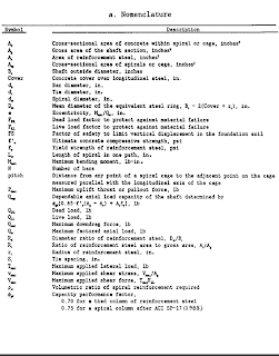
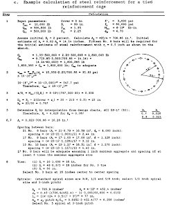
Table 2-7 describes evaluation of the shaft cross section and percent reinforcement steel required for adequate shafi strength under design loads.....

(1) The maximum bending moment, Mmax is required to determine the amount of reinforcement steel to resist bending. The maximum factored vertical working load, Qw, and the estimate of the maximum applied lateral load, Rmax, are used to calculate Mmax. The full amount of reinforcing steel is not required near the bottom of the pile because bending moments are usually negligible near the pile bottorn.

(2) Load factors are applied to the design live and dead loads to ensure adequate safety against structural failure of the shaft. An example is worked out in Table 2-7c for FDL =  1.35 and FLL = 2.25 for a shaft supporting a bridge column.

(3) The minimum reinforcement steel, normally recommended, is 1 percent of the total cross-sectional area of drilled shaft expected to be exposed along their length by scour or excavation. Reinforcement steel should be full length for shafts constructed in expansive soi1 and for shafts requiring casing while the hole is excavated. Shaft diameter should be increased if the reinforcement steel required to resist bending such that adequate voids through the reinforcement cage will be provided to accommodate the maximum aggregate size of the concrete.

(4) The maximum applied axial load should also include maxirnum downdrag forces for a shaft in compressibie soil and the maximum uplift thrust for a shaft in expansive soil. Uplift thrust may develop before the full structural load is applied to the shaft. Under such conditions, smaller amounts of reinforcement may be used if justified on the basis of relevant and appropriate computations.

Table 2-7 Minimum Requirements for Drilled Shaft Design.

Structural Design of Drilled Shafts.

Most drilled shaft foundations will be subject to lateral loads, bending moments, and shear stresses in addition to compressive stresses frorn vertical loads. Eccentrically vertical applied loads can generate additional bending moments.

a. Eccentricit.  If bending moments and shears are not specified, the minimum eccentricity should be the larger of 2 inches or O.1 Bs, where Bs is the shaft diarneter, when tied cases of reinforcement steel are used and 1 inch or O.05Bs then spiral cages are used. The rninimum eccentricity should be the maximum perrnitted deviation of the shaft out of its plan alignment that does not require special computations to calculate the needed reinforcement if larger eccentricities are allowed.


b. Design example. Table 2-7 describes evaluation of the shaft cross section and percent reinforcement steel required for adequate shafi strength under design loads.....