Showing posts with label BUILDING. Show all posts

Tuesday, April 19, 2025

ELEMENTS OF A BUILDING


The following are the basic elements of a building:


  1. Foundation
  2. Plinth
  3. Walls and columns
  4. Sills, lintels and chejjas
  5. Doors and windows
  6. Floors
  7. Roofs
  8. Steps, stairs and lifts
  9. Finishing work
  10. Building services.


The functions of these elements and the main requirement of them is presented in this article.


1. Foundation: Foundation is the most important part of the building. Building activity starts with digging the ground for foundation and then building it. It is the lower most part of the building. It transfers the load of the building to the ground. Its main functions and requirements are:

(a) Distribute the load from the structure to soil evenly and safely.

(b) To anchor the building to the ground so that under lateral loads building will not move

(c) It prevents the building from overturning due to lateral forces.

(d) It gives level surface for the construction of super structure.


2. Plinth: The portion of the wall between the ground level and the ground floor level is called plinth. It is usually of stone masonry. If the foundation is on piles, a plinth beam is cast to support wall above floor level. At the top of plinth a damp proof course is provided. It is usually 75 mm thick plain concrete course.


The function of the plinth is to keep the ground floor above ground level, free of dampness. Its height is not less than 450 mm. It is required that plinth level is at least 150 mm above the road level, so that connections to underground drainage system can be made.


3. Walls and Columns: The function of walls and columns is to transfer the load of the structure vertically downwards to transfer it to foundation. Apart from this wall performs the following functions also:


(a) It encloses building area into different compartments and provides privacy.

(b) It provides safety from burglary and insects.

(c) It keeps the building warm in winter and cool in summer.


4. Sills, Lintels and Chejjas: A window frame should not be directly placed over masonry. It is placed over 50 mm to 75 mm thick plain concrete course provided over the masonry. This course is called as sill. Lintels are the R.C.C. or stone beams provided over the door and window openings to transfer the load transversely so as to see that door or window frame is not stressed unduly. The width of lintels is equal to the width of wall while thickness to be provided depends upon the opening size. Chejja is the projection given outside the wall to protect doors and windows from the rain. They are usually made with R.C.C. In low cost houses stone slabs are provided as chejjas. The projection of chejja varies from 600 mm to 800 mm. Sometimes drops are also provided to chejjas to improve acsethetic look and also to get additional protection from sun and rain.


5. Doors and Windows: The function of a door is to give access to different rooms in the building and to deny the access whenever necessary. Number of doors should be minimum possible. The size of the door should be of such dimension as will facilitate the movement of the largest object likely to use the door.


Windows are provided to get light and ventilation in the building. They are located at a height of 0.75 m to 0.9 m from the floor level. In hot and humid regions, the window area should be 15 to 20 per cent of the floor area. Another thumb rule used to determine the size and the number of windows is for every 30 m3 of inside volume there should be 1 m2 window opening.


6. Floors: Floors are the important component of a building. They give working/useful area for the occupants. The ground floor is prepared by filling brick bats, waste stones, gravel and well compacted with not less than 100 mm sand layer on its top. A lean concrete of 1 : 4 : 8, 100 mm thick is laid. On this a damp proof course may be provided. Then floor finishing is done as per the requirement of the owner. Cheapest floor finish for a moderate house is with 20 to 25 mm rich mortar course finished with red oxide. The costliest floor finish is mossaic or marble finishing.


Other floors are usually of R.C.C. finished as per the requirements of the owner.


7. Roof: Roof is the top most portion of the building which provide top cover to the building. It should be leak proof.


Sloping roof like tiled and A.C. sheet give leak proof cover easily. But they do not give provision for the construction of additional floor. Tiled roof give good thermal protection.


Flat roofs give provision for additional floors. Terrace adds to the comfort of occupants. Water tanks can be easily placed over the flat roofs.


8. Step, Stairs and Lifts: Steps give convenient access from ground level to ground floor level. They are required at doors in the outer wall. 250 to 300 mm wide and 150 mm rise is ideal size for steps. In no case the size of two consecutive steps be different. Number of steps required depends upon the difference in the levels of the ground and the floor. Stairs give access from floor to floor. They should consists of steps of uniform sizes.


In all public buildings lifts are to be provided for the conveniences of old and disabled persons. In hostels G + 3 floors can be built without lifts, but in residential flats maximum floors permitted without lifts is only G + 2. Lift is to be located near the entrance. Size of the lift is decided by the number of users in peak hours. Lifts are available with capacity 4 to 20 persons.


9. Finishing: Bottom portion of slab (ceiling), walls and top of floor need smooth finishing with plaster. Then they are provided with white wash, distemper or paints or tiles. The function of finishing work is:


(a) Give protective cover

(b) Improve aesthetic view

(c) Rectify defective workmanship

(d) Finishing work for plinth consists in pointing while for floor it consists in polishing.


10. Building Services: Water supply, sanitation and drainage works, electric supply work and construction of cupboards and show cases constitute major building services.


For storing water from municipal supply or from tanker a sump is built in the house property near street. From the sump water is pumped to over head tanks placed on or above roof level so as to get water all the 24 hours. Plumbing work is made so as to get water in kitchen, bathrooms, water closets, sinks and garden taps.


For draining rain water from roofs, down take pipes of at least 100 mm diameters should be used. Proper slopes should be given to roof towards down take pipe. These pipes should be fixed at 10 to 15 mm below the roof surface so that rain water is directed to the down take pipe easily.


The sanitary fittings are to be connected to stone ware pipes with suitable traps and chambers. Stone ware pipes are then connected to underground drainage of municipal lines or to the septic tank.


Many carpentry works are required for building service. They are in the form of showcases, cupboards, racks etc.


Electric supply is essential part of building services. The building should be provided with sufficient points for supply of lights, fans and other electric gadgets.

Friday, December 17, 2024

Building Innovations

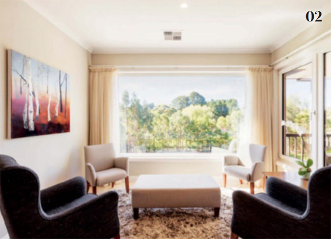
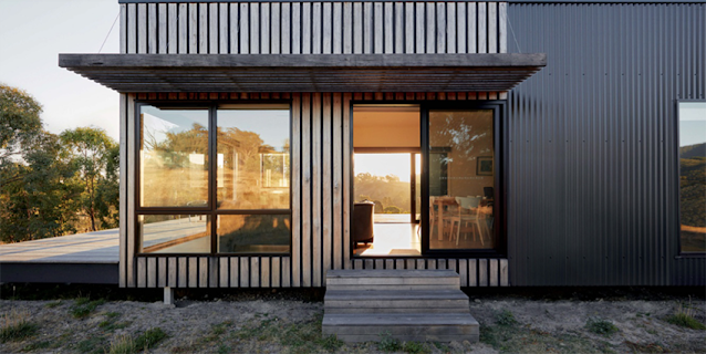
According to industry experts, matters of energy efficiency, innovative building technologies and evolving design trends are the key factors shaping our homes as we enter 2020. Prefab construction is a growing trend, with the advantages of quality control, design flexibility and reduced labour costs making it a highly desirable choice — for new builds in particular.


Energy efficiency continues to be a high priority as home builders look to offset rising energy costs and find a more eco-friendly construction footprint. Glazing is one of the biggest arenas tackling this concern, along with thermally efficient green building materials and the wide use of water-wise fittings and fixtures in order to conserve water.


In home design trends, experts are predicting that the current thirst for clean lines and a minimalist aesthetic will continue to meet the needs of Australian homeowners as we move into a new decade. Innovations in small space design will surge as block sizes get smaller and vertical living increases — making balconies and courtyards the new greenspace of an increasingly urban population. And home automation will become more commonplace as we take control of our living environment and automate everything!


1. HEMPCRETE

HEMPCRETE


The market for green building products is a growth market (no pun intended). Eco-conscious home builders everywhere are seeking materials that result in a non-toxic habitat with a low environmental impact, are sustainable, and offer improved thermal efficiency for future energy savings. Luckily for these conscientious people, the range of eco-friendly construction materials available today tick many of these boxes, including hempcrete.


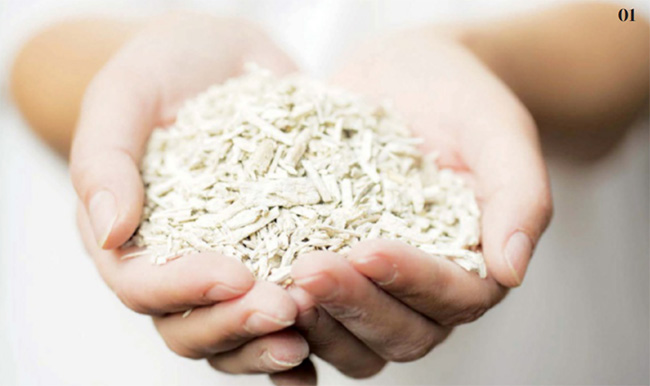
A biocomposite material made from hemp shiv (the inner woody core of the industrial hemp plant) and lime, hempcrete is used to construct insulating walls, floors and roofs, or make construction blocks and panels. A sustainable building product, it produces excellent thermal insulation that results in reduced energy consumption.


Hempcrete is BAL FZ-rated for use in bushfire prone areas and is termite and mould resistant. It is also permeable or ‘breathable’, regulating indoor humidity by absorbing/desorbing water vapour to provide a comfortable and healthy interior atmosphere, and locks in carbon (approx. 100kg of carbon per square metre of hempcrete).


Presenting a textured finish in its natural state that is both attractive and durable, hempcrete can also be covered with a render to achieve a smoother, more modern aesthetic if desired.


Dedicated to the use of sustainable and eco-friendly materials, hemp building specialist Hemp Lime Constructions (HLC) use Tradical®Hempcrete in their work. A highperformance, low impact building method, hempcrete allows HLC to meet the needs of its most discerning clients while staying true to its commitment to bio-based construction.


2. ENERGY-EFFICIENT GLAZING

ENERGY-EFFICIENT GLAZING


Taking up a large percentage of a home’s surface area, glazing is a major construction consideration contributing to security and thermal efficiency. With up to 40 percent of a home’s heat loss and up to 87 percent of its heat gain occurring via windows, it is essential that well-engineered glazing be expertly fitted to ensure optimal energy gains. In addition, superior window design provides a solid security measure and ensures the architectural vision of a home.


Setting the benchmark in energy efficient glazing since 1990, Paarhammer windows and doors are custom made in Australia to meet structural performance and water penetration standards of the highest level. Unique framing, sealing and secure metal-to-metal locking systems, combined with double or triple glazing, produce windows and doors with high sound protection and premium energy efficiency.


Suitable for passive house construction, with a variety of glass options including Low-E and switchable I-glass, Paarhammer’s Architectural Timber Range of high performance windows offer design excellence and unparalleled security and strength.


With natural insulation properties, timber is both versatile and attractive. Available in a variety of plantation grown timbers, including FSC® certified timber, and offering a range of styles from tilt n’ turn windows to sliding doors, Paarhammer’s Architectural Timber collection can be custom designed to fit everything from modern constructions to heritage renovations.


3. INFRARED SAUNAS

INFRARED SAUNAS


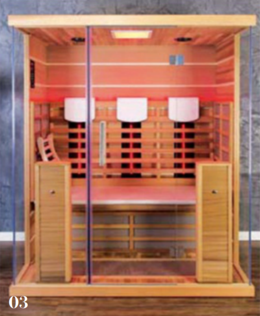
More than just a Scandi design influence, infrared saunas offer a plethora of health benefits relevant to combatting today’s concerns regarding health and wellbeing.


Whether it’s dealing with pain from arthritis, managing conditions such as fibromyalgia or injury related pain, saunas have long proven an effective method in the relief of symptoms. Saunas have also been proven to increase blood circulation, cleanse the skin, relieve stress, improve quality of sleep, aid in recovery after exercise, and contribute to weight loss for overall improved health.


The growing interest in building saunas into Australian homes can be attributed to our belief in the benefits of a healthy lifestyle, making a personal infrared sauna an investment not only in good health but also in your home’s value.


Infrared saunas work by heating the body directly, penetrating into the skin and increasing cardiovascular output that in turn removes heavy metals and toxins from the body through sweat.


With an interestin supporting health and wellbeing, iHealth Saunas offer a collection of quality infrared saunas to meet a range of needs. From a compact unitideal for apartments to a spacious three-person unit, each iHealth sauna can be safely constructed into any home. Builtto Australian electrical safety standards, each unit’s high-efficiency, low-EMF carbon heating element effectively disperses infrared energy across a wide surface area for a cost-effective and comfortable sauna experience.


4. SOLAR ENERGY

SOLAR ENERGY


With the demand for cost-effective and eco-friendly energy options on the rise, solar power solutions for home energy needs is a burgeoning industry. In a country where sunshine reigns day after day, solar power is a solid investment, and today’s advancements in technology are making it easier for households to participate.


Recently launched in Australia by SENEC, the Home V3 Hybrid solar battery is a revolution in home energy consumption, providing households with up to 90 percent solar-power self-sufficiency, saving thousands a year in energy costs with excess power pumped back into the grid.


Of the 20 percent of homes in Australia fitted with solar panels, only 3 percent had batteries connected at the time of installation — usually due to a lack of benefits that warrant the price. The new generation SENEC hybrid solar battery delivers a range of benefits never seen before, including a 20-year warranty, combined PV inverter and battery inverter, PV overvoltage protection safety, three-tier remote monitoring, unlimited solar recharging cycles, and retrofit capacity.


Designed, engineered and manufactured in Germany, the SENEC Home V3 Hybrid battery takes up just 0.29m2; a compact unit that is easily installed without specialist tools. An intelligent management system, this hybrid solar battery is a revolution in energy storage and consumption.


5. PREFAB PRECISION

PREFAB PRECISION


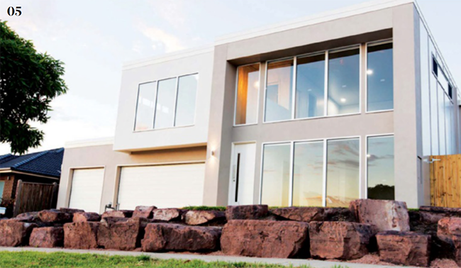
Insulated wall panel and cladding products are the leading-edge frontier in residential and commercial construction. Reducing building costs via improved manufacturing methods and reduced onsite labour costs, prefab construction materials are a cost-efficient and sustainable method of erecting a house in today’s competitive and eco-conscious market.


Taking prefab seriously, Bondor, a leader in complete thermal building solutions, produce LuxeWall®; a lightweight architectural walling system. Admired for its range of luxury finishes and high-performance insulation options, LuxeWall®offers builders a sustainable choice that helps them meet project timeframes and budget parameters.


Suitable for use as a feature wall, decorative façade or upper/lower storey walling, LuxeWall ®(50mm and 75mm) is a Codemark® accredited concealed fix system, finished with the market-first UniSmart architectural trim and capping system.


LuxeWall® (50mm) has a 60 minute fire rating (FRL 60/60/60) for residential applications when used as a boundary wall system, and is suitable for multiresidential and commercial use that requires a 90 minute fire rating (FRL 90/90/90).


With excellent thermal efficiency properties, this pre-finished walling product is versatile and offers flexibility to meet a range of needs. Able to take a range of matte and metallic painted finishes or texture coatings, LuxeWall®provides the freedom to achieve a plethora of design visions and meet council or developer requirements.

To find the right combination, consult with Bondor to guarantee LuxeWall® meets your building and design specifications.


Is The Future of Construction Modular?

Is The Future of Construction Modular?


Prefabrication of parts and off-site construction of modules has been a practice for more than 10 years. However, in the last couple of years, we’ve seen changes in the construction industry move more towards bringing the work in-house.


La Trobe Tower in Melbourne, with 44 storeys and standing at 133m, is now officially Australia’s tallest prefabricated building. The residential tower was constructed in only 16 months. Similar projects are going on in the UK and the US.


The experts behind all these projects share the same vision: the future is modular. They believe the technology needed to have modular construction finally exists and they plan to show it. The problem is that many people still don’t believe in this way of building, even though, since the 1990s, government reports were saying that modular construction is safer and faster, while not compromising the quality of the construction.


Unfortunately, the majority of buildings worldwide are still made the old-fashioned way — on site. What keeps the hope of having a modular future alive is many large-scale projects around the world that are built using this technology. Projects such as Google Headquarters, which was designed by Bjarke Ingels; Creekside Wharf in Greenwich, which is the tallest modular structure in the UK; and the La Trobe Tower, which is the highest in Australia.


The benefits of modular construction are any. It is a safer way of building but at the same time it can be both cheaper and faster. Contractors are now able to start working on foundations on-site and start with the manufacturing process in the factory. Experts have calculated this can enable projects to be finished up to 50 per cent faster than with traditional construction.


Furthermore, modular construction and prefabrication lowers the amount of material waste, plus it allows constructors to continue production even in bad weather. This type of development also enables us to rethink the use of buildings since, in the future, modular structures could be disassembled and shipped to other locations for reuse.


The experts find modular construction to be excellent when it comes to managing quality. Whatever is manufactured on-site can vary in quality, especially if the builder doesn’t have strict quality control. However, when you produce something in a factory, it is easier to establish control over quality and make sure that every single modular piece is up to standard.


On the other hand, the builder will have to worry about the transport of modular elements from the factory to the construction site. Tolerances would have to be higher in the factory since every module needs to be shipped.


So, what’s slowing down the adoption of modular construction? The benefits are apparent but it’s still far from everyday use. Experts agree there are many reasons for this, most of them being economical, technical and financial.


Currently, there aren’t enough experts who can be present on the construction site to monitor a build. Traditional construction enables you to adjust everything you need on-site during the build. The fact that the industry is hesitant to adopt this new technology means there’s no need yet for experts in this field.


Another issue builders have is that modular construction requires a company to have its own factory to make modules. Construction companies don’t hesitate to invest, but this kind of upfront investment requires lots of funds that may or may not pay off in the longterm. For a factory like this to be economically viable, it needs to have consistently highvolume turnover.


Finally, it’s the market that drives the change. In post-war Europe, modular construction was the best solution for urban areas as it was fast and efficient. At that time the demand for housing was high but there simply weren’t enough skilled workers to work on-site


THINK OUTSIDE THE BOX


A great example of modern prefabrication being used in construction is the Crowne Plaza hotel extension at Changi Airport. Singapore’s construction regulator stated that at least 65 per cent of tower superstructures must use PPMC (prefabricated prefinished modular construction). The PPMC helped lower the number of workers required on-site by 40 per cent. Furthermore, the construction of one floor took three to four days, instead of two to three weeks.


Designers have been interested in modular construction for a long time. They are fascinated by the possibility of adding new modules where needed, or for their structures to be able to adapt to everchanging urban environments. It all points to the construction industry of the future being modular. As the robot technology develops, one day it will enable fast and accurate production of prefabricated modules. As the manufacturers and designers around the world are getting familiar with the technology, we might see some new and exciting structures being built. The market is always looking for novel and cheaper ways to build. In a world where there aren’t enough skilled workers, modular might be the way to go.


Designers and manufacturers are slowly embracing the idea and with the current lack of skilled workers available to carry out traditional house builds, prefab buildings might just be the solution.


Wednesday, March 19, 2014

Buildings: Thermal examples

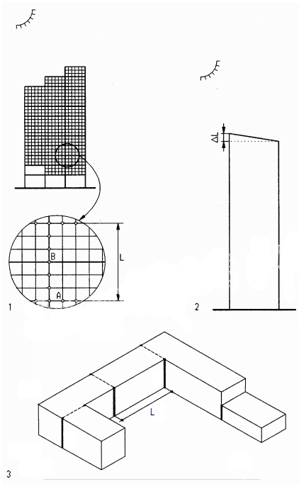
1 Curtain wall
Assume: 

Aluminum curtain wall, find required expansion joint


Thermal strain


2  High-rise building, differential expansion
Assume:

Steel columns exposed to outside temperature


Differential expansion


3  Masonry expansion joints 
(masonry expansion joints should be at maximum L = 100’)
Assume

Buildings: Thermal examples

Monday, August 26, 2013

DETAILING SANDWICH MEMBRANES

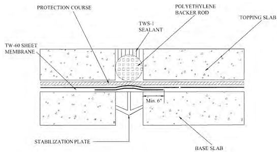
Expansion or control joints should be installed in both the structural slab portion and the protection layer. Providing for expansion only at the structural portion does not allow for thermal or structural movement of the topping slab.

This can cause the topping slab to crack, leading to membrane deterioration. Refer to Figs. 3.62 and 3.63 for proper detailing. Membranes should be adhered only to the structural deck, not to topping layers, where unnecessary stress due to differential movement between the two layers will cause membrane failure.


Expansion joint detailing for topping slab construction.
FIGURE 3.62 Expansion joint detailing for topping slab construction.
FIGURE 3.63 Expansion joint detailing for topping slab construction.
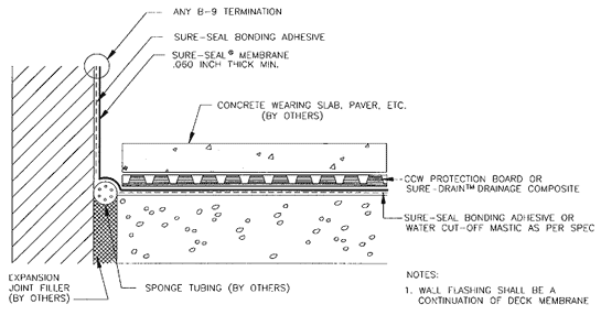
Waterproof membranes should be adequately terminated into other building enve- lope components before applying topping and protection layers. The topping is also tied into the envelope as secondary protection.

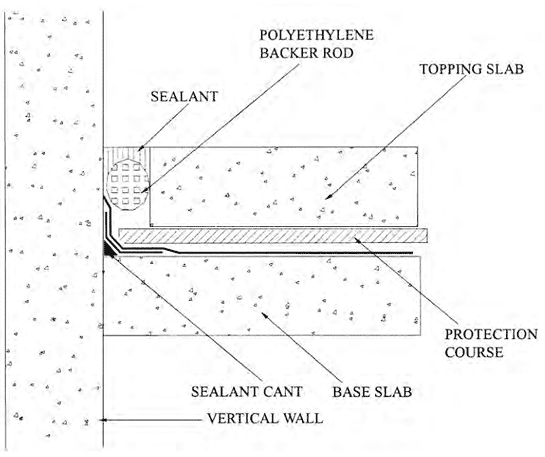
Control or expansion joints are installed along topping slab perimeters where they abut other building components, to allow for adequate movement (Fig. 3.64). Waterproof membranes at these locations are turned up vertically, to prevent water intrusion at the protection layer elevation. Refer to Fig. 3.65 for a typical design at this location.


Perimeter expansion joint detailing for sandwich-slab membranes.
FIGURE 3.64 Perimeter expansion joint detailing for sandwich-slab membranes.
Transition detailing for sandwich-slab membranes.
FIGURE 3.65 Transition detailing for sandwich-slab membranes.

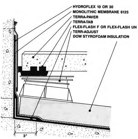
When pavers are installed as the protection layer, pedestals are used to protect the membrane from damage. Pedestals allow leveling of pavers, to compensate for elevation deviations in pavers and structural slabs (Fig. 3.66).

 Pedestals permit the leveling of the walking surface on sloped structural decks using sandwich-slab membranes.
FIGURE 3.66 Pedestals permit the leveling of the walking surface on sloped structural decks
using sandwich-slab membranes.

At areas where structural slabs are sloped for membrane drainage, pavers installed directly over the structural slab would be unlevel and pose a pedestrian hazard.

Pedestals allow paver elevation to be leveled at these locations. Pedestals are manufactured to allow four different leveling applications, since each paver typically intersectsfour pavers, each of which may require a different amount of shimming (Fig. 3.67).


FIGURE 3.67 Pedestal detail.

If wood decking is used, wood blocking should be installed over membranes so that nailing of decking into this blocking does not puncture the waterproofing system. Blocking should runwith the structural drainage design so that the blocking does not prevent water draining.

Tile applications, such as quarry or glazed tile, are also used as decorative protection layers with regular setting beds and thin-set applications applied directly over membranes.

With thin-set tile installations, only cementitious or liquid-applied membrane systems are used, and protection board is eliminated. Tile is bonded directly to the waterproof membrane.


Topping slabs must have sufficient strength for expected traffic conditions. Lightweight orinsulating concrete systems of less than 3000 lb/in2 compressive strength are not recommended.

If used in planting areas, membranes should be installed continuously over a structural deck and not terminated at the planter walls and restarted in the planter. This prevents leakage through the wall system bypassing the membrane. See Fig. 3.68 for the differences in these installation methods. Figure 3.69 represents a typical manufacturer detail for a similar area.

FIGURE 3.68 Planter detailing for split-slab membrane.
FIGURE 3.69 Typical detail for planters on decks.

Using below-grade membranes for above-grade planter waterproofing is very common, especially on plaza decks. While these decks themselves are often waterproofed using the techniques described in this chapter, the planter should in itself be made completely water- proof to protect the building envelope beneath or adjacent to the planter.

Figures 3.70 and 3.71 detail the typical application methods of waterproofing above- grade planter areas. Note that each of these details incorporates the use of drainage board to drain water towards the internal planter drain. Since these areas are watered frequently, drainage is imperative, in this case, not only for waterproofing protection but also for the health of the vegetation planted in the planter.


FIGURE 3.70 Typical detailing for above-grade planter areas.


FIGURE 3.71 Typical detailing for above-grade planter areas.
Figure 3.72 shows the application of liquid membrane to planter walls as does Fig. 3.73. In the latter note how difficult the use of a sheet good system would be in this particular application. Whenever waterproofing above-grade planters with tight and numerous changes-in- plane or direction, liquid applied membranes are preferred over sheet-good systems as the preferred “idiot-proof” application. The con- tinual cutting of sheets in these smaller appli- cations results in a corresponding number of seams that emphasize the 90%/1% principle. Liquid applications are seamless and can prevent the problems associated with sheet-good installation in small planter areas.


Selection of a protected system should be based on the same performance criteria as those for materials used with below-grade applications. For example, cementitious systems are rigid and do not allow for structural movement. Sheet-goods have thickness controlled by premanufacturing but contain seams; liquid-applied systems are seamless but millagemust be controlled.

Monday, July 29, 2013

DECK-COATING APPLICATION

When deck coatings are being applied at a job site, it is the only time when golf shoes are mandatory attire! Liquid deck coatings are required to be squeegee-applied to ensure sufficient and uniform millage. The millage rate is too thick for spray applications, which cannot also provide the uniform thickness required.

During application the squeegee is pushed, not pulled, to prevent the blade end of the squeegee from being pulled down too hard against the substrate and applying too thin a wet millage of material. Pushing of the squeegee blade maintains the blade in an upright position and a uniform millage application.

This pushing of the squeegee requires that the mechanic walk through the applied material, thus requiring the golf shoes so as not to damage the installation and have shoes stick to the wet membrane. The material self-levels after installation, so that any minute impressions the golf-shoe spikes leave are quickly covered by the material.

Most deck coatings also require that the material be immediately back-rolled after initial squeegee application to further ensure uniformity of millage. These applicators must also wear the golf shoes, as do those applying the aggregate that forms the wearing surface in the top coat applications. Figure 3.21 pictures the application process of a typical deck coating application.

Deck-coating application. Note the pushing of squeegees in the background, back-rolling of coating and spreading of the aggregate by hand in the foreground. All crew members are wearing golf shoes.
FIGURE 3.21 Deck-coating application. Note the pushing of squeegees in the background, back-rolling
of coating and spreading of the aggregate by hand in the foreground. All crew members are wearing golf
shoes.


Substrate adhesion and proper substrate finishing are critical for successful deck-coating applications. In general substrates must be clean, dry, and free of contaminants. Concrete substrates exhibiting oil or grease contamination should be cleaned with a biodegradable degreaser such as trisodium phosphate. Contaminants such as parking-stall stripe paint should be removed by mechanical grinder or sandblasting (Figs. 3.22 and 3.23).

 Mechanical removal of contaminants.
FIGURE 3.22 Mechanical removal of contaminants.

Substrate has been scarified prior to deck-coating application to ensure proper adhesion.
FIGURE 3.23 Substrate has been scarified prior to deck-coating application to ensure proper adhesion.
For new concrete substrates, a light broom finish is desirable. Surface laitance, fins, and ridges must be removed. Honeycomb and spalled areas should be patched using an acceptable nonshrink grout material.

Coatings should not be applied to exposed aggregate or reinforcing steel. If present, these areas should be properly repaired. Concrete surfaces, including patches, should be cured a minimum of 21 days before coating application. Use of most curing compounds is prohibited by coating manufacturers, since resins contained in curing compounds preventadequate adhesion. If present, substrates require preparatory work, including sandblasting, or acid etching with muriatic acid. Water curing is desirable, but certain manufacturers allow use of sodium silicate curing agents.

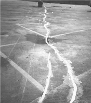
Substrate cracks must be prepared before coating application (Fig. 3.24). Cracks less than 1 16 in wide should be filled and detailed with a 4-in band of nonflow base coat. Larger cracks, from  1 2 in to a maximum of 1-in width, should be sawn out and filled with ure- thane sealant (Fig. 3.25). Moving joints should have proper expansion joints installed with coating installed up to but not over these expansion joints. Refer to Figs. 3.26 and 3.27 for typical expansion joint detailing.

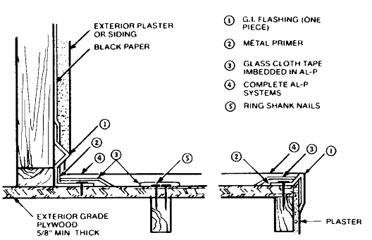
Substrates should be sloped, to drain water toward scuppers or deck drains. Plywood surfaces should be swept clean of all dirt and sawdust. Plywood should be of A-grade only, with tongue and groove connections (Fig. 3.28). Only screw-type fasteners should be used, and they should be countersunk. The screw head is filled with a urethane sealant and troweled flush with the plywood finish (Fig. 3.29). As these coatings are relatively thin, 60–100 mil dry film, their finish mirrors the substrate they are applied over.

Therefore, if plywood joints are uneven or knots or chips are apparent in the plywood, they also will be apparent in the deck-coating finish.
FIGURE 3.24 Crack repair prior to deck-coating application.


FIGURE 3.29 Deck-coating details for plywood deck applications.


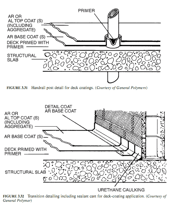
Metal surfaces require sandblasting or wire-brush cleaning, then priming immediately afterward (Fig. 3.30). Aluminum surfaces also require priming (Fig. 3.31). Other substrates such as PVC, quarry tile, and brick pavers should be sanded to roughen the surface for adequate adhesion. Sample test areas should be completed to check adhesion on any of these substrates before entire application.


For recoating over previously applied deck coatings, existing coatings must be thoroughly cleaned with a degreaser to remove all dirt and oil. Delaminated areas should be cut out and patched with base coat material. Before reapplication of topcoats, a solvent is applied to reemulsify existing coatings for bonding of new coatings.

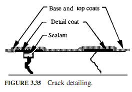
All vertical abutments and penetrations should be treated by installing a sealant cove, followed by a detail coat of nonflow material (Figs. 3.32, 3.33, and 3.34). If a joint occurs between changes in plane such as wall-to-floor joints, an additional detail coat is added or reinforcement. Figures 3.35 and 3.36 show typical installation procedures for this work.

With new construction, detail coats of base coat membrane are turned up behind the facing material (e.g., brick cavity wall), followed by coating and detailing to the facing material. This allows for double protection in these critical envelope details. At doors or sliding glass doors, coating is installed beneath thresholds before installation of doors.

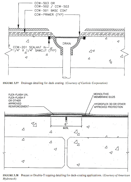
Figure 3.37 shows application procedures at a deck drain.

For applications over topping slabs with precast plank construction, such as double-T, a joint should be scored at every T-joint. These joints are then filled with sealant and adetail coat of material is applied allowing for differential and thermal movement. Refer to Figs. 3.38 and 3.39 for typical installation detail at these areas.

Base coats are installed by notched squeegees for control of millage, typically 25–40 mil dry film, followed by back-rolling of materials for uniform millage thickness (Fig. 3.40).

Following initial base-coat curing, within 24 hours intermediate coats, topcoats, and aggregates are installed (Fig. 3.41).

Aggregate, silica sand, and silicon car- bide are installed in intermediate or final topcoats or possibly both in heavy traffic areas. On pedestrian decks grit is added at a rate of 4–10 lb square (100 ft^2) of deck area.

In traffic lanes, as much as 100–200 lb of aggregate per square is added.

Aggregate is applied by hand seeding (broadcasting) or by mechanical means (Fig. 3.42). If aggregate is added to a topcoat, it is back-rolled for uniform thickness of membrane and grit distribution. With installations of large aggregate amounts, an initial coat with aggregate fully loaded is first allowed to dry.

Excess aggregate is then swept off, and an additional topcoat is installed to lock in the grit and act as an additional protective layer. See Fig. 3.43 for aggregate comparisons.

Intermediate coats usually range in thickness from 10 to 30 mil dry film, whereas top coats range in thickness from 5 to 20 mil. Refer to Figs. 3.44 and 3.45 for typical millage requirement. Final coats should cure 24–72 hours before traffic is allowed on the deck,paint stripping is installed, and equipment is moved onto the deck.

Approximate coverage rates for various millage requirements are shown in Table 3.21. Trowel systems are applied to considerably greater thickness than liquid-applied systems. Troweled systems range from 1 /8–1/ 4 in total thickness, depending upon the aggregate used.

Other than applications of acrylic coatings, manufacturers require primers on all substrates for improved membrane bonding to substrates. Primers are supplied for various substrates, including concrete, wood, metal, tile, stone, and previously coated surfaces. Additionally, priming of aggregate or grit is required before its installation in the  coating. Some primers must be allowed to dry completely (concrete); others must be coated over immediately (metal). In addition to primers, some decks may require an epoxy vapor barrier to prevent blistering from negative vapor drive.

Because of the volatile nature and composition of deck-coating materials, they should not be installed in interior enclosed spaces without adequate ventilation. Deck coatings are highly flammable, and extreme care should be used during installation and until fully cured. Deck coating requires knowledge- able, trained mechanics for applications, and manufacturer’s representatives should review details and inspect work during actual progress.

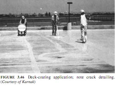
Figure 3.46 demonstrates proper deck coating application, and Fig. 3.47 demon- strates the various stages of deck-coating application.


Monday, July 22, 2013

DECK-COATING CHARACTERISTICS

Deck coatings bond directly to concrete, wood, or metal substrates. This prevents lateral movement of water beneath the coatings, as is possible with sheet good systems. Once cured, coatings are nonbreathable and blister if negative vapor drive is present. This is the reason deck coatings, with the exception of acrylic and epoxies, are not recommended for slab-on-grade applications. Specifically, moisture in soils is drawn up into a deck by capillary action, causing blistering in applied deck coatings. In the same manner, blistering occurs in deck coatings applied on upper deck portions of sandwich-slab membranes due to entrapped moisture and negative vapor drive. In both cases, an epoxy vapor barrier prime coat should be installed to protect deck-coating systems from being subjected to this vapor drive.

Physical properties of deck coatings vary as widely as the number of systems available. Important considerations to review when choosing a coating system include tensile strength, elongation, chemical resistance, weathering resistance, and adhesion properties. Different installation types, expected wearing, and weathering conditions require different coating types.

High tensile strength is necessary when a coating is subject to heavy wear including vehicular traffic or forklift traffic at loading docks. Tensile strengths of some deck coatings exceed 1000 lb/in^2 (tested according to ASTM D-412) and are higher for epoxy coatings. This high tensile strength reduces the elongation ability of coatings.

Elongation properties range from 200 percent (for high-tensile-strength top coats) to more than 1000 percent (for low-tensile-strength base coats). For pedestrian areas where impact resistance and heavy wear is not expected, softer, higher elongation aromatic ure- thanes are used. Sun decks subject to impact from lawn chairs and tables would be better served by a coating between the extremes of high and low tensile strength.

Chemical resistance can be an important consideration under certain circumstances.
Parking garage decks must have coatings resistant to road salts, oil, and gasoline. A pedes- trian sun deck may be subjected to chlorine and other pool chemicals. Testing for chemical resistance should be completed according to recognized tests such as ASTM D-471.

Weathering resistance and ultraviolet resistance are important to coatings exposed to the elements such as on upper levels of a parking garage. These areas should be protected by the ultraviolet-resistant properties of coatings such as an aliphatic urethane. Weathering characteristics can be compared with accelerated weathering tests such as ASTM D-822.

Other properties to consider on an as-needed basis include adhesion tests, solvent odor for interior uses, moisture vapor transmission, and fire resistance.

Once installed, the useful life of deck coatings depends upon proper maintenance as well as traffic wear. Heavily traveled parking garage decks and loading docks will wear faster than a seldom-used pedestrian deck area. To compensate, manufacturers recommend a minimum of one to as many as three additional intermediate coat applications. Additional aggregate is also added for greater wear resistance (Fig. 3.20).

FIGURE 3.20 Suggested aggregate texture layout for maximum protection of deck coating.
FIGURE 3.20 Suggested aggregate texture layout for
maximum protection of deck coating.
With proper installation, deck coatings should function for upward of 5 years before requiring resealing. Resealing entails cleaning, patching existing coatings as required, reapplying top coatings, and, if required, adding intermediate coats at traffic lanes. Proper maintenance prevents coatings from being worn and exposing base coatings that cannot withstand traffic or exposure.

Exposed and unmaintained deck-coating systems require complete removal and replacement when repairs become necessary. Chemical spills, tears or ruptures, and improper usage must also be repaired to prevent unnecessary coating damage. Maintaining the top coat or wearing surface properly will extend the life cycle of a deck-coating system indefinitely.

Deck coatings are also effective in remedial waterproofing applications. If a sandwich- slab membrane installed during original construction becomes ineffective, a deck coating can be installed over the topping slab provided proper preparatory work is completed.

Deck coatings can also be successfully installed over quarry and other hard-finish tile sur- faces, precast concrete pavers, and stonework. With any special surfacing installation, proper adhesive tests and sample applications should be completed.

Monday, July 15, 2013

Deck Coating - Sheet systems

While they do not fit the description of a deck coating per se, there are balcony and deck waterproofing systems that are available in sheet materials that provide waterproofing capabilities. There are a variety of systems available, including those that require the sheet embedded in a trowel- or spray-applied acrylic or resin material, and those that are act as a complete system.

The latter is a vinyl product, similar to a typical interior vinyl flooring product with the exception that the product is improved to withstand exterior weathering and of course water infiltration. The system is vulnerable for leakage at the seams, following the 90%/1% principle. If seaming is adequately addressed, including the necessary vertical turn-ups, the product can be an effective barrier system. These systems make excellent candidates for remedial application, as they can hide considerably more substrate imperfections than the liquid systems discussed previously. These systems can also be applied to wood substrates and make excellent choices for residential applications including apartment projects.

Many systems combine the properties of the liquid-applied systems with sheet good reinforcing for “belt and suspenders” protection. The limiting factor is cost, as the more material and layers a system requires for effectiveness, the more the final in-place cost rises. Table 3.20 summaries the advantages and disadvantages of using sheet systems for waterproofing applications.
Sheet Systems

Monday, July 8, 2013

Deck Coating Formulations: Acrylics, Cementitious coatings, Epoxy, Asphalt overlay, Latex, Neoprene, Hypalon, Urethane

Acrylics

Acrylics are not waterproof coatings, but act as water-repellent sealers. Their use is primarily aesthetic, to cover surface defects and cracking in decks. These coatings have low elastomeric capabilities; silica aggregate is premixed directly into their formulations, which further lowers their elastic properties. These two characteristics prevent acrylics from being true waterproof coatings.

The inherent properties of acrylics protect areas such as walkways or balconies with no occupied areas beneath from water and chloride penetration. In addition to concrete sub- strates, acrylics are used over wood or metal substrates, provided that recommended primers are installed. Acrylics are also used at slab-on-grade areas where urethane coatings are not recommended.

Sand added in acrylic deck coatings provides excellent antislip finishes. As such, they are used around pools or areas subject to wet conditions that require protection against slips and falls. Acrylics are not recommended for areas subject to vehicular traffic. Some manufacturers allow their use over asphaltic pavement subject only to foot traffic, for aesthetics and a skid-resistant finish. (See Table 3.14.)


Cementitious

Cementitious deck coatings are used for applications over concrete substrates and include an abrasive aggregate for exposure to traffic. These materials are supplied in prepacked and premixed formulations requiring only water for mixing. Cementitious coatings are applied by trowel, spray, or squeegee, the latter being a self-leveling method.

Cementitious systems contain proprietary chemicals to provide necessary bonding and waterproofing characteristics. These are applied to a thickness of approximately  1 8 in and will fill minor voids in a substrate. A disadvantage of cementitious coatings, like below- grade cementitious systems, is their inability to withstand substrate movement or cracking.

They are one-step applications, with integral wearing surfaces, which require no primers and are applicable over damp concrete surfaces.

Modified acrylic cementitious coatings are also available. Such systems typically include a reinforcing mesh embedded into the first coat to improve crack-bridging capabilities. Acrylics are added to the basic cement and sand mixture to improve bonding and performance characteristics.

Cementitious membrane applications include the dry-shake and power-trowel methods previously discussed in Chap. 2. Successful applications depend on properly designed, detailed, and installed allowances for movement, both thermal and differential. For cementitious membranes to be integrated into a building envelope, installations should include manufacturer-supplied products for cants, patching, penetrations, and terminations. (See Table 3.15.)


Epoxy

As with acrylics, epoxy coatings are generally not considered true waterproof coatings.
They are not recommended for exterior installations due to their poor resistance to ultraviolet weathering. Epoxy floor coatings have very high tensile strengths, resulting in low elastomeric capabilities. These coatings are very brittle and will crack under any movement, including thermal and structural.

Epoxy coatings are used primarily for interior applications subject to chemicals or harsh conditions such as waste and water treatment plants, hospitals, and manufacturing facilities. For interior applications not subject to movement, epoxy floor coatings provide effective waterproofing at mechanical room floor, shower, and locker room applications.

Epoxy coatings are available in a variety of finishes, colors, and textures, and may be roller- or trowel-applied.

Epoxy deck coatings are also used as top coats over a base-coat waterproof membrane of urethane or latex. However, low-movement capabilities and brittleness of epoxy coatings limit elastomeric qualities of waterproof top coats. (See Table 3.16.)


Asphalt

Asphalt overlay systems provide an asphalt wearing surface over a liquid-applied membrane. The waterproofing base coat is a rubberized asphalt or latex membrane that can withstand the heat created during installation of the asphalt protective course. Both the waterproof membrane and the asphalt layers are hot-applied systems.

Asphalt layers are approximately 2 in thick. These systems have better wearing capabilities due to the asphaltic overlay protecting the waterproof base coating.

The additional weight added to a structure by these systems must be calculated to ensure that an existing parking garage can withstand the additional dead loads that are created.

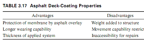
Asphalt severely restricts the capability of the waterproof membrane coating to bridge cracks or to adjust to thermal movement. Additionally, it is difficult to repair the waterproofing membrane layers once the asphalt is installed. There is no way to remove overlays without destroying the base coat membrane. Asphaltic systems are not recoatable. For maintenance, they must be completely removed and reinstalled. (See Table 3.17.)


Latex, neoprene, hypalon

Deck coatings are available in synthetic rubber formulations, including latex, neoprene, neoprene cement, and hypalon. These formulations include proprietary extenders, pigments, and stabilizers. Neoprene derivatives are soft, low-tensile materials and require the addition of a fabric or fiberglass reinforcing mesh. For traffic-wear resistance, this reinforcing mesh enhances in-place performance properties such as elongation and crack-bridging capabilities.

Reinforcing requires that the products be trowel applied rather than roller or squeegee applied.
Trowel application and a finish product thickness of approximately  1 4 in increase the in-place costs of these membranes. They also require experienced mechanics to install the rubber derivative systems. Trowel applications, various derivatives, and proprietary formulations provide designers with a wide range of textures, finishes, and colors.

Rubber compound coatings have better chemical resistance than most other deck-coating systems. They are manufactured for installation in harsh environmental conditions such as manufacturing plants, hospitals, and mechanical rooms. They are appropriate in both exterior and interior applications.

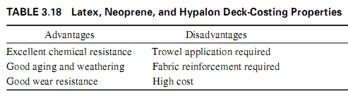
Design allowances must be provided for finished application thickness. Deck protrusions, joints, wall-to-floor details, and equipment supports must be flashed and reinforced for membrane continuity and watertightness. Certain derivatives of synthetic rubbers become brittle under aging and ultraviolet weathering, which hinders waterproofing capabilities after installation. Manufacturer’s literature and applicable test results should be reviewed for appropriate coating selection. (See Table 3.18.)


Urethanes

Urethane deck coatings are frequently used for exterior deck waterproofing. These are available for both pedestrian and vehicular areas in a variety of colors and finishes. Urethane systems include aromatic, aliphatic, and epoxy-modified derivatives and formulations.

Aliphatic materials have up to three times the tensile strength of aromatics but only 50 percent of aromatic elongation capability. Many manufacturers use combinations of these two materials for their deck-coating systems. Aromatic materials are installed as base coats for better movement and recovery capabilities; aliphatic urethane top coats make for better weathering, impact resistance, and ultraviolet resistance.

Epoxy urethane systems are also used as top coat materials. These modified urethane systems provide additional weathering and wear, while still maintaining necessary waterproofing capabilities.

Urethane coatings are applied in two or more coats, depending upon the expected traffic wear. Aggregate is added in the final coating for a nonslip wearing surface. An installation advantage with urethane systems is their self-flashing capability. Liquid-applied coatings by brush application are turned up adjoining areas at wall-to-floor junctions, piping penetrations, and equipment supports and into drains.

Urethane coatings are manufactured in self-leveling formulations for applications control of millage on horizontal surfaces. Nonflow or detailing grades are available for vertical or sloped areas. The uncured self-leveling coating is applied by notched squeegees to control thickness on horizontal areas. At sloped areas, such as the up and down ramps of parking garages or vertical risers of stairways, nonflow material application ensures proper millage. If self-leveling grade is used in these situations, material will flow downward and insufficient millage at upper areas of the vertical or sloped portions will occur.

Nonflow liquid material is used to detail cracks in concrete decks before deck-coating application. Cracks wider than  1 /16 in, which is the maximum width that urethane materials bridge without failure, are sawn out and sealed with a urethane sealant. This area is then detailed 4 in wide with nonflow coating.

In addition, urethane coatings are compatible with urethane sealants used for cants between vertical and horizontal junctions, providing a smooth transition in these and other changes of  plane. This is similar to using wood cants for roof perimeter details (see Table 3.19).

Older Posts Home