Showing posts with label SITE EXPLORATION. Show all posts

Site Investigation Report.

Tweetear
The report should contain the information gained in reconnaissance, survey, investigation, testing and soil survey recommendations and the design engineer’s recommendations. Since the report is the property of the client his permission should be obtained for its distribution to invited main and appropriate specialist sub-contractors and any public authority collecting soil data.

The report will contain a mass of information which must be presented in an orderly, easily digested manner and written in clear, unambiguous, good English. Since most  of the intended readers are mainly visually orientated, the use of photos, maps, soil profiles, borehole logs and other visual aids is to be recommended as is the tabulation of test results and other information. The report is not a thesis nor a scientific treatise, but a factual report with comments, opinions and recommendations based on the interpretation

of the facts from experience. The facts and opinions must be clearly separated. Since the report is likely to be subject to hard and frequent usage it is advisable to bind it between stiff covers rather than merely stapling a mass of A4 sheets.

The script, drawings and layout should be checked and  re-checked just as carefully as calculations and drawings from the design office.

A recommended procedure is as follows:

(1) Collect data, categorize it and rough out a preliminary draft.
(2) Edit the draft and seek methods of visual presentation and tabulation.
(3) Polish re-draft and check for improvements in pres- entation, check for typing errors and appearance.

1 Factors affecting quality of report  The restraints of time and funding that need to be allowed for in the investigation have been discussed in earlier  sections. There are other factors which can affect the quality of the investigation, recommendations and the engineering judgement. Among those which may affect some engineers are:

(1) Uncritical acceptance of well-presented opinion, results of sophisticated (but not necessarily relevant) tests and over- and unqualified respect for some specialists.
(2) Allowing site difficulties to dictate the investigation in an attempt to keep the investigation simple and cheap.
(3) Lack of recognition that piling and other foundation techniques can be used to economic advantage even on good sites.
(4) Lack of recognition that some fills, possibly upgraded by ground improvement techniques, can provide an adequate and economic bearing strata.
(5) Lack of appreciation that advances in structural design can accommodate relatively high settlements.
(6) Under-estimation of the importance of the designer,  at least, visiting the site during the investigation or  dismissal of trial pits as unscientific or out-dated.

2 Sequence of report  Foundation reports follow the normal sequence of items of engineering reports in having a title, contents list,  synopsis, introduction, body of the report, conclusions and recommendations. Lengthy descriptions of tests and similar matters are best dealt with in appendices and the test results tabulated in the body of the report. The client tends to read the synopsis and recommendations; the main and sub-contractors concentrate on the body of the report and the design office on its conclusions and recommendations.

If the brief imposed such limitations on cost and time allocation for the investigation that the engineer was not able to carry out an adequate survey this should be tactfully pointed out. It should also be made clear in such cases that the engineer’s conclusions and recommendations are qualified – this is unfortunately advisable in the present  litigatious climate.

3 Site description  This, as far as possible, should be given on small-scale plans showing site location, access and surrounding area. The proposed position of the buildings and access roads should be shown. The site plan should also show the general layout and surface features, note presence of existing buildings, old foundations and previous usage, services, vegetation, surface water, any subsidence or unstable slopes, etc.

Written description of the site exposure (for wind speed regulations) should be given together with records of any flooding, erosion and other geographical and hydrographic information.

Geological maps and sections should, when they are necessary, be provided, noting mines, shafts, quarries, swallowholes and other geological features affecting design and construction.

Photographs taken on the site, preferably colour ones, can be very helpful and should be supplemented by aerial  photographs if considered necessary.

4 The ground investigation

(1) Background study and location of holes. This should give  a full account of the desk-top study, examination of  old records, information from local authorities, public utilities and the like, and the field survey. It should detail the position and depth of trial pits and boreholes, equipment used and in situ testing and information.

(2) Boreholes, trial pits and soil profiles. This section will be mainly a visual presentation of the logs and profiles together with colour photographs of the trial pits.

Where possible, written information should be given in note form on the soil profiles.

(3) Soil tests. This should list the site and laboratory tests drawing attention to any unusual, unexpected or special results. The results of the tests should be tabulated, for ease of reference, and diagrams of such information as particle size distribution, pressure–void ratio curves and Mohr’s circles should be given. If such form of presentation is not fully adequate then test descriptions and results should be given in an appendix.

5 Results  This must give details of ground conditions, previous use of site, present conditions, groundwater and drainage pattern.

The tests must give adequate information to determine the soil’s bearing capacity, settlement characteristics, behaviour during and after foundation construction and, where necessary, its chemical make-up and condition.

6 Recommendations  This is both comment on the facts and also opinions based on experience; the difference should be made clear. Since the discussion is usually a major part of the report it should
be broken down into sections for ease of reference and readability.

The first section should briefly describe the proposed main and subsidiary structures and their loading, a description and assessment of the ground conditions and the types of appropriate foundations.

The second section should advise on foundation depths, pressures, settlements, discuss alternatives giving advantages, disadvantages and possible problems keeping in mind cost and buildability considerations.

Typical main recommendations are:

(1) Safe bearing capacities at various depths, estimates  of total and differential settlement and time-span of
settlement.
(2) Problems of excavation (fills, rock, water ingress, toxic and combustible material).
(3) Chemical attack on concrete and steel by sulfates and chlorides or acids within soil.
(4) Flotation effect on buoyant or submerged foundations.
(5) Where the proposed structure houses plant which could vibrate or impact shock the soil, the effect on the soil must be assessed.
(6) Details of any necessary geotechnical processes to improve the soil’s properties.
(7) Where piling is necessary, information must be given on founding level, possible negative skin friction, obstructions, appropriate type and installation of piles and the effects of piling on adjacent constructions and existing buildings.
(8) Where a foundation is subject to lateral loading, the magnitude and position of the loading must be given
together with the skin friction between the soil and the passive resistance of the soil.
(9) Where retaining walls are required, information is needed on active pressure, passive resistance, sur-
charge, factor of safety against slip circle failure, possible landslides or slips.
(10) Where road construction is involved requiring CBR values, etc., though this is outside the scope of this book.

The final section should give firm recommendations on the foundation type or types to be adopted.

Soil Samples and Soil Profiles.

Tweetear
It is a wise precaution to take more soil samples than necessary to determine the ground conditions (and increasing the frequency of samples does not proportionally increase the cost of the soil survey). It is not however necessary to test every single sample. If the surface soil is weak and underlain by good rock or dense gravel there may be little point in testing the weak surface soil if piling down to the good strata is proposed.

Soil profiles (section through boreholes) are extremely helpful in enabling the designer to visualize the ground
conditions. This valuable aid is, in the authors’ opinion, too often given inadequate attention in site investigations.

Many foundation failures can be traced back to faulty  visualization of the ground conditions due to inadequate soil profiles or misinterpretation of them. A typical soil profile is shown in Fig. 3.7.

Most experienced designers would tend to study the soil profile first before reading the site report, studying the test results and checking other data. This makes for efficiency, better assessment of site conditions, improved judgement of data, it warns of problems and can indicate the need for possible further investigation.

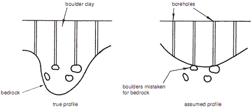
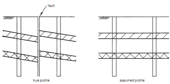
Some typical misinterpretations or inadequate data leading to false conclusions and similar errors are shown in Fig. 3.8 (see also Figs 2.28, 2.29 and 2.31).

Fig. 3.7 Soil profile for a typical site.


Fig. 3.8 Misinterpretation of soil profile 
(Weltman, A.J. & Head, J.M., Site Investigation Manual, CIRIA (1983),

Fig. 2.28 Mistaken bedrock.


Fig. 2.29 Unchecked fault.


Fig. 2.31 Folded strata mistaken for level strata.

Recording Information – Trial Pit and Borehole Logs and Soil Profiles.

Tweetear
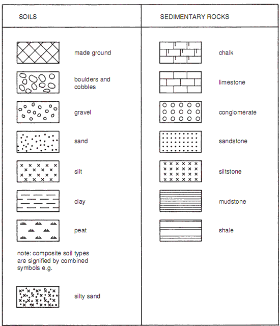
Before embarking on expensive laboratory testing of soil samples it is advisable to record (log) the information gained on site in order to plan the test programme. To facilitate the reading of logs and boreholes the soils and rocks should be indicated by standardized symbols. Widely accepted diagrammatic symbols are given in Fig. 3.4.

A typical trial pit log of the engineer’s observations is given in Fig. 3.5.

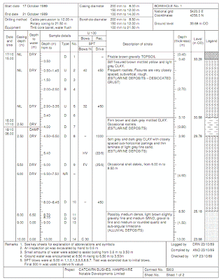
A borehole log should give details of the foreman driller’s log, the observations of the supervising engineer and the results of any site tests. A typical borehole log is shown in Fig. 3.6.

Trial pits, trenches and boreholes should be given reference numbers, located on plan, their ground level noted and the date of excavation recorded. It is advisable to record the  following additional information:

(1) Type of rig, diameter and depth of bore or width of bucket.
(2) Diameter and depth of any casing used and why it was necessary.
(3) Depth of each change of strata and a full description of the strata. (Was the soil virgin ground or fill?)
(4) Depths at which samples taken, type of sample and sample reference number.
(5) In situ test depth and reference number.
(6) The levels at which groundwater was first noted;  the rate of rise of the water; its level at start and end of
each day. (When more information on permeability, porewater pressure, and the like is required, then it is vitally important that the use of piezometers should  be considered.)
(7) Depth and description of obstructions (i.e. boulders), services (drains) or cavities encountered.
(8) Rate of boring or excavation (useful to contractors and piling sub-contractors as such information gives some guidance in ease of excavation or pile driving).
(9) Name of supervising engineer.
(10) Date and weather conditions during investigation.

Fig. 3.4 Recommended symbols for soils and rocks


Fig. 3.5 Typical trial pit log (Weltman, A.J. & Head, J.M., Site Investigation Manual, CIRIA (1983),


Fig. 3.6 Example of a typical borehole log (BS 5930, Fig. 22).

Field (site) Testing of Soils.

Tweetear
No matter how carefully soil samples are taken, stored, transported to a laboratory and tested, some disturbance is possible and even likely – and therefore many engineers prefer the alternative of testing the soil in situ. As with  sampling techniques there have been advances in sophistication and variety of field testing techniques and the most common types are briefly described here.

Site testing has come a long way from kicking the clay at the bottom of a trial pit with the heel of the investigator’s shoe – though this can still be a useful, if crude, assessment when carried out by an experienced engineer familiar with local conditions.

In foundation design less is known of soil as a structural material than is known of concrete and steel. It is not possible to analyse and forecast, with certainty, the stresses in the soil or the soil’s reaction to those stresses, since the foundation loading can only be a reasonable assessment.

Foundation design is therefore based not solely on analysis but also needs the application of sound engineering judgement.

In a sensible and valuable search to understand the material it must be tested and some researchers have devoted their careers to this essential cause. In each of the following field and laboratory tests there has been extensive research, literally thousands of learned papers and many international conferences – some devoted to just one test, for example, see References 5 and 6. It is not possible therefore in a  book on foundation design to discuss fully in depth any one test; discussion is limited to the broader considerations.

Furthermore the site and laboratory testing of soils is  the contractual responsibility of the soil survey specialist.

Hence the following sections outline and summarize the tests and the main references are given for designers wishing for more detailed information. Experience is necessary to estimate what and how to test, the test results need engineering judgement in assessing their application and relevance and in forecasting estimated behaviour – for none  of the tests give scientifically accurate results applicable to the actual strata under the real pressure. The theories, as in structural theory, are based on simplifying assumptions not fully related to the reality of practice. But to dismiss tests and theory and rely on outdated  rules of thumb  methods is inappropriate to modern structures and is as foolish as blind faith in science.

1 Standard Penetration Test (SPT)  The SPT is a useful method of indicating the relative  density of sands and gravels. It is based on the fact that the denser the sand or gravel the harder it is to hammer a peg into it. A standard weight is dropped a defined distance on a tube, with either a split tube or a cone head (cone penetration test, CPT), placed in the borehole. The tube is driven 450 mm into the soil and the number of hammer-blows taken to drive the tube into the last 300 mm of soil is termed its  N  value. Care in interpreting the result is particularly  necessary where boulders, very coarse gravel or bricks in backfill may be present, for the measurement may be of the resistance of the obstruction and not of the soil.

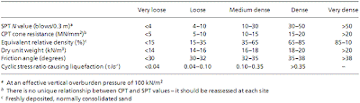
Approximate values of the relationship between sand properties and  N  values are given in Table 3.3 and a
summary of the test is given in Table 3.4. CIRIA Publication  The Standard Penetration Test (SPT): Methods and Use(7) is a comprehensive reference.

2 Vane test  If a garden spade is driven into clay and then rotated it will effectively shear the clay and the higher the shear resistance of the clay then the greater the force (torque) required to rotate the spade. This is the principle of the vane test.

The vane is a cruciform of four blades fixed to the end of the boring tube’s rod. It is pushed into the undisturbed soil at the base of the borehole or trial pit and the torque required to rotate the vane is measured. Table 3.5 gives a summary of the test.

When the height of the vane is twice its diameter, D(m), the relationship between shear strength of the soil, τ, and the maximum applied torque, M(kN m), is generally:


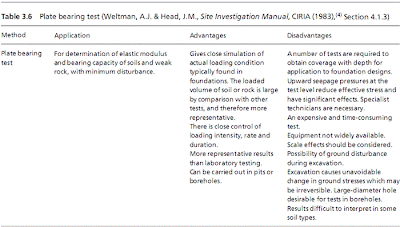
3 Plate bearing test  A plate, of known area, can be placed at the bottom of a trial pit or borehole and loaded. The settlement of the soil under load can be measured and also the pressure required to cause
shear failure of the soil. The test is summarized in Table 3.6.

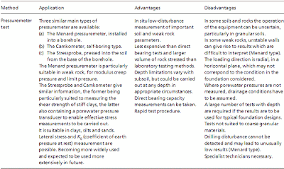
4 Pressuremeters  A pressuremeter could be considered as basically a vertical plate test. If an expanding cell is placed in a borehole and pumped up to exert pressure against the sides of the bore then the stronger the soil the greater the pressure required to expand the cell. Summaries of different pressuremeters are given in Table 3.7.

5 Groundwater (piezometers and standpipes)  The presence of moisture in, and the magnitude of moisture content of, soils has a pronounced effect on soil properties and behaviour. Since the moisture content can vary so too can the soil. It is essential therefore to investigate the ground-water conditions and possible variation. Groundwater variations are likely on coastal, estuarine and tidal river sites; sites subject to artesian conditions and variable water-table levels; sites with permeable granular soil where bored piles or bentonite diaphragm walls are to be used, and particularly sites founded on fills.

The rate of seepage of groundwater into pits and bores together with level and variations in level should be
recorded. Piezometers or standpipes should be employed when groundwater problems are anticipated.

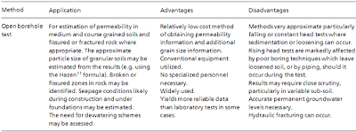
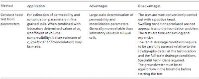
A standpipe can at its simplest be the open borehole, and the outline of the test is summarized in Table 3.8.
Piezometers, of varying sophistication, are basically perforated tubes lined internally with porous tubing, and details are summarized in Table 3.9.

6 Other field tests  There are a number of developments, refinements and adjustments to the above tests as well as geophysical  tests, aerial infra-red photography, video photography in boreholes, etc. These newer tests can sometimes be less expensive, less time-consuming and yield more information than the traditional tests. The interested reader should refer to specialist soil mechanics literature for details.


 Table 3.3 Relationship between N values and sand properties


 Table 3.4 Standard Penetration Test (Weltman, A.J. & Head, J.M.,  
Site Investigation Manual, CIRIA (1983)


 Table 3.5 Vane test (Weltman, A.J. & Head, J.M., Site Investigation Manual, CIRIA (1983)


Table 3.6 Plate bearing test (Weltman, A.J. & Head, J.M., Site Investigation Manual, CIRIA (1983)


 Table 3.7 Pressuremeter test (Weltman, A.J. & Head, J.M., Site Investigation Manual, CIRIA (1983)


 Table 3.8 Open borehole test (Weltman, A.J. & Head, J.M., Site Investigation Manual, CIRIA (1983)


Table 3.9 Piezometer test (Weltman, A.J. & Head, J.M., Site Investigation Manual, CIRIA (1983)

Trial Pit Layout.

Tweetear
Trial pits should be located near to the proposed or existing foundations but not so close as to adversely affect foundation excavation or to disturb existing underground services and drains. They should straddle the proposed site of the building to give cross-sections along the major axes.

Generally five or more pits are necessary.

Trial pits yield such information as soil classification, how well the sides of the excavation stand up, the position of  the water-table, whether seepage of groundwater will be a problem, the ease of  level, ram and trim, the invert of the excavation, possible deterioration of the soil on exposure to the atmosphere, the presence and depth of fills, and the ease or difficulty of excavation. (Boreholes can discover sandstone, for example, which contractors will tend to price with high excavation rates yet the trial pit excavator may well be able to excavate the rock easily.) Percussion boring may compress thick layers of peat into thin slices and it is not uncommon to receive descriptions such as ‘sand with traces of peat’ when trial pits would disclose the layer of peat within the stratum of sand. For this reason it is good practice to excavate several trial pits in the vicinity of proposed boreholes so as to check the correlation of the findings of the two techniques. It is easier to take good undisturbed soil samples from a trial pit than a borehole; to carry out in situ tests (such as the standard penetration test and shear vane test) and to give the soil the apocryphal kick with the heel to estimate its strength.

Trial pits should be excavated down to at least the expected excavation level and on difficult sites (subject to thorough boring, sampling and testing) the information obtained can be used as a useful additional aid to foundation design and construction. They can also provide a visual check on the likely reliability of test information. If the sides of the pit are liable to collapse and access is required, then propping should be carried out to protect the investigator, or the sides should be battered or stepped by the excavator.

Where the site is open to access by people or animals, the pits should be backfilled or protected at the end of each day. Where it is necessary to check, over a period of time, seepage or deterioration, the pit should be planked over and covered with tarpaulins or otherwise adequately protected.

The position, ground level and invert level of the  pits should be noted together with the findings of soil classification, properties and levels of the strata. Colour photographs of the sides of the pits can be useful and  the photographs have increased value if a ranging rod is included to confirm the scale. Where the presence of services is suspected, trial pits can be used to detect them, preferably by careful hand-digging.

Where, from past experience, the ground is known to be firm clay or dense gravel of considerable depth, then trial pits may be all that is necessary to investigate the suitability of the site for a lightly loaded structure. They must be dug to an adequate depth, to prove the stratum and to detect soft lenses or layers likely to be affected by the foundation loading. Trial pit information is also invaluable in determining the borehole grid layout.

Borehole Layout.

Tweetear
Three bores are the minimum necessary to determine the dip of a plane strata (where known with confidence to be plane) and as a rough guide this is the minimum for a proposed investigation (it is almost self-evident not to have too many!). The more bores drilled then the more is known about the soil and the risks of meeting difficulties and the greater surety and economy of the foundation design. But obviously once enough is known to design an economical foundation then any further bores are an added-on cost to the project. This assumes, of course, that the stratum  are accurately recorded, described and positioned, etc. by  a competent supervisor during the drilling operations.

Inadequate or inexperienced supervision could lead to expensive errors.

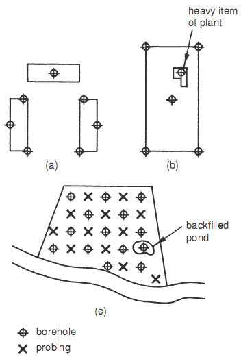
On large sites, say for an industrial estate, when the positions of structures have not been defined it is advisable to establish a grid of boreholes as shown in Fig. 3.1 (c). The spacing of the grid depends upon the site study and reconnaissance. A common grid spacing is about 30 m but, if the site is well-known and of uniform strata, the spacing may be increased. If the site is unknown, suspect and variable, the spacing should be decreased. Where the findings are not uniform and difficulties are unknown, or are expected, then the grid centres should be closed up. Where the site has been mined, an irregular grid is advisable since the
workings may be on a regular grid.

The boreholes enable soil profiles (cross-sections) to be drawn noting the strata classification, thickness and level, and samples taken from the borehole enable the properties of the soil in each strata to be examined. The bores can also enable observations to be made on groundwater levels and variations. The depth of the borehole depends on:

(1) The foundation load. Light, single-storey structures founded on known firm ground of thick strata need
investigation to a depth of about 3 m – and this can be done effectively by trial pits. Tall, heavily loaded structures may need bores taken down to proven firm soil of adequate strata thickness.

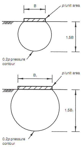
(2) The width of the structure. At a depth of 1.5 times the width of the structure the vertical pressure on the soil can be about 20% of the foundation contact pressure.

Closely spaced (i.e. at centres less than about 4 times their width) strip or pad foundations due to pressure
distribution overlap would have the same pressure effect at such a depth as a raft foundation. The wider the structure the deeper the effect of vertical pressure (see Fig. 3.2) and it may be necessary to bore down to
1.5 times the width of the structure.

(3) Whether there is a possible need for piling. Then the bores should be taken down to 3 m below preliminary estimated pile base level.

(4) Whether there is a possible need for foundations to be taken down to bedrock. It is advisable to prove that it is in fact bedrock and not boulders (in glacial or flood deposits or quarry backfill) or relatively thin layers of cemented rock-hard soils (shales in mining areas). This can mean that drilling should continue for at least 3 m into the rock. There have been a number of spectacular failures in mistaking isolated boulders as bedrock.

Fig. 3.1 Typical borehole layouts for (a) multi-storey
flats, (b) factory building, (c) large development area
where building layout is not decided.


Fig. 3.2 Vertical pressure at a depth of 1.5 times
foundation width.

Soil Investigation.

Tweetear
A soil survey can range from a few trial pits inspected by the designer and the soil untested by laboratory analysis to an extensive borehole investigation with deep and numerous bores and extensive sampling and testing of the soil usually by specialist investigation contractors.

The factors affecting the investigation are the amount of existing information available, the known uniformity or likely variability of the sub-soil in the area, the foundation loading and the type of structure, the general topography and likely groundwater conditions of the site.

Subsidiary factors such as the amount of time and money available, the site access and other matters should not inhibit the planning of a thorough (and as reliable as is  reasonably possible) investigation.

No matter what kind of investigation is carried out, the authors, from experience, recommend the digging of  trial pits as a first stage. Trial pits have over the past few decades fallen into almost contemptuous dismissal by some  with the increased sophistication of boring techniques, increased cost of labour in digging pits and increased awareness of the limitations of pits (e.g. they do not detect underlying soft soils which can be affected by foundation loading). But during the same period there has been increased adaptability, mobility, etc., of relatively small excavators. Such machines can easily excavate and backfill a dozen pits, or trenches, in a day to a depth of 3–6 m and can be hired on a daily basis at cost-effective rates. The cost of replacing services damaged during excavation can be substantial, especially in the case of optical fibre cables, and the responsibility for adequate insurance cover should therefore not be overlooked.

1 Borehole layout  Three bores are the minimum necessary to determine the dip of a plane strata (where known with confidence to be plane) and as a rough guide this is the minimum for a proposed investigation (it is almost self-evident not to have too many!)...

2 Trial pit layout  Trial pits should be located near to the proposed or existing foundations but not so close as to adversely affect foundation excavation or to disturb existing underground services and drains. They should straddle the proposed site of the building to give...

3 Hand augers  Hand augers are sometimes used in preliminary reconnaissance since the equipment is light, cheap and immediately available, and so that overall, time can be saved in planning a full survey. They can, in soft to firm soils, bore a hole about 150 mm diameter to a depth of 3–4 m and provide disturbed samples of the soil. They can be used in restricted spaces, which is useful in investigating foundation failure below a confined basement. However the work can be physically hard, somewhat slow and very difficult, or impossible, in stony clays and gravels.

4 Boring  Most bores are carried out using light cable percussion plant backed up, when necessary, with rotary coring and other equipment and attachments. The cable percussion rig commonly uses an 8 m high tripod and employs a friction winch to raise and lower the boring tubes and tools. Rotary coring is used when hard shales, boulders or rock strata are encountered.

There is an increasing variety of plant, sampling methods and tools, with particular advantages in cost, quality of sampling, speed of operation, use in conditions of limited access or headroom, etc., and the choice of rig is affected by the likely soil conditions to be encountered.

5 Backfilling of trial pits and boreholes  If bores and particularly pits are positioned sufficiently close to the proposed structure so as to affect foundation excavation then they should be carefully backfilled. A strip footing founded on firm clay and passing over an inadequately compacted backfilled trial pit is effectively passing over a soft-spot. A borehole can sometimes act as an artesian well or as a seepage point. Trial pits or trenches should be backfilled in layers with controlled compaction. Boreholes should be backfilled, as the casing is withdrawn, with selected excavated material and punned with a weighted shell. Grouting boreholes is sometimes necessary with 4 : 1 cement : bentonite. The quality of backfilling of trial pits is however often unreliable and if the pits are close to the foundation they should be re-excavated along with the foundation excavation and backfilled again after completion of foundation construction.

6 Soil sampling  Samples of the soil are taken from boreholes and trial pits so that the soil can be described and tested. There are two types of samples:

• Disturbed samples. Samples taken from boring tubes or hand excavated from the sides and bottom of trial pits where the soil structure is disturbed  i.e. broken up, cut, pressed, etc. These samples are placed in airtight jars (similar to screw lid jam-jars), labelled to identify the borehole or pit number, the position of the sample, the number given to it in the records, and the date taken.

Failure to label samples in standard format will obviously lead to confusion at the laboratory so the label must be secure and the information noted on it must be legible and written in waterproof ink.

Disturbed samples are tested to determine, mainly,  the type and description of the soil. The sampling and
testing of disturbed samples is relatively inexpensive and the test results are used to determine the test
programme of undisturbed samples.

If the disturbed samples are to be used to determine the moisture content of the soil it is important that the
sample jar should be completely filled by the sample to prevent it drying out. As a further precaution the air- tight cap should be wound round by a water-resistant
tape.

• Undisturbed samples. The term undisturbed  is somewhat  of a misnomer for even with refined equipment it is difficult to obtain a true undisturbed sample. Certainly, undisturbed samples are generally superior to disturbed samples in representing more closely the actual in situ structure and moisture content of the soil.

The soil structure and moisture content are important factors in soil strength and behaviour under load. Disturbed soil is trimmed from the ends of the sample tubes, the ends are then covered by foil and waxed before screwing on the tube cap or lid. Labels, giving the same information as for disturbed samples, should be placed both inside  the cap and outside the tube.

Undisturbed samples are tested to determine mainly the strength and behaviour of the soil. Undisturbed  samples are relatively expensive to obtain and test and it is generally not necessary to test all the samples. Nevertheless it is advisable to obtain at least one sample for each stratum at each borehole. The test programme is fully determined after study of borehole logs and soil profiles.

7 Storage of samples  Preferably samples should be sent to the testing laboratory immediately – and this, of course, is not always possible.  If they are just left lying around the site they could be sub- ject to drying out, impact, etc. so they should be carefully stacked and stored in a cool and somewhat moist site hut or container box.

8 Frequency of sampling  The soil investigation engineer, preferably with the design engineer’s report on site study, reconnaissance and trial pit findings if available, can decide on an economic frequency
of sampling. Generally undisturbed soil samples should be taken at 1.5 m intervals and at change of stratum level and disturbed samples taken at 1 m intervals. This is not a rigid rule and should be varied to suit soil and foundation conditions. When trial pits have not been excavated, these intervals should be halved from ground level to 2–3 m below the anticipated depth of foundation excavation. It is at or near ground level that the soil is usually most variable due to exposure to weather, change in moisture conditions and
variations in the water-table level.

The foreman driller should keep a log noting the type (classification) of soil, its depth, change of stratum level,
position of obstructions, changes of soil conditions within a stratum, groundwater level, seepage and similar information. Experienced and reliable foremen drillers are becoming, unfortunately, rarer and it is essential that the soil survey investigator backs up the foreman’s observations by adequate inspection visits by site supervision engineers.

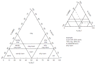
The log should give a continuous description of the soil in the borehole from ground level to base of bore. It is important that the foreman is aware of the standard classification and description used in References 3 and 4 and does not solely employ (the often colourful) local terms such as cowbelly, sludge, mucky clay, cobbly clay. While these terms may be well-known to local engineers they can be unfamiliar and totally misleading to others. The local terms are often an invaluable guide to experienced local engineers in describing the soil and its properties and it would be a pity in some cases if these were to die out. Where there is a mixture of clay, silt and sand the MIT (Massachusetts Institute of Technology) classification should be used (see Fig. 3.3).


Fig. 3.3 The MIT classification for clay, silt and sand.

9 Appointment of specialist soil investigator  Most design offices do not have sufficient demand for soil
investigations to warrant the capital costs of obtaining site and laboratory equipment, nor the current costs of employing site and laboratory personnel. It is therefore generally necessary to appoint specialist firms – and this may not always be as easy as it might appear.

The work should be carried out by competent soil survey specialists of good reputation, staffed by experienced engineers (and drillers) who will not only supervise the borings but also the testing and can be relied upon to report accurately and advise soundly on their findings. The specialist firm should carry adequate indemnity. In the past a number of excellent firms have been driven out of business by cut-throat competition from ‘cowboy’ firms savagely undercutting sensible rates. This is a deplorable situation which could cost the client, in the end, far more than has been  saved by employing such firms. (On more than one occasion the authors’ practice has been asked to investigate foundation failures and found that borehole logs are a  complete fabrication – because they were not done!)

There should be detailed discussion between the design engineer and the soil specialist on the survey specification, cost and time. Soil specialists may not have wide experience of foundation design, behaviour of structures, economics of alternative designs, construction difficulties, etc., so the discussion is essential for reliable investigations.

It is also strongly advisable for the design engineer in  person to inspect the boring during progress to see firsthand the condition of the soil samples and sampling methods.

Preliminary Site Reconnaissance and Site Walkabout.

Tweetear
With the above information, presented clearly in an easily digested report, the senior design engineer should visit the site and the immediate neighbourhood to develop a feel for the site. It is sometimes advisable for the senior engineer to visit the site before the ‘study of existing information’ so that assistants can be advised on important points, such as where there is a particular need for detailed study and the like in carrying out the investigation.

The senior engineer would note the soil type and condition in any adjoining cuttings (road, rail and stream banks), adjacent buildings showing signs of foundation distress, uneven ridge lines, tilting or settled boundary walls,  unstable or creeping slopes, depressions in the ground  and their possible cause, type and changes in vegetation  on  green  sites, previous use and ground behaviour of  abandoned sites and similar points.

Typical warning signs of possible foundation difficulties are:

(1) Unused sites in built-up pre-war housing estates which can indicate that local builders had encountered site problems.

(2) Flat, rubble-strewn derelict sites in inner-city housing areas which may be riddled with backfilled base-
ments, cellars and bomb craters (unexploded bombs remain a distinct possibility).

(3)
Dry, firm ground in summer which is sprouting marsh grass may be a quagmire in winter. Many cases of
landslip slope failure are caused by water, so the identification of possible sources of groundwater on both historic maps and on site is most important.

(4) Undeveloped areas around the outskirts of towns and not encroaching on green-belt boundaries which can indicate problem sites.

(5) Backfilled quarries; domestic refuse and industrial waste tips.

(6) Bumpy, irregular ground surface which can be indicative of glacial terminal moraine deposits.

(7) Evidence of ‘bell-working’ where mineral seams are near ground level.

(8) ‘Blow holes’ in chalk soils.

(9) Subsidence in areas of brine extraction.

(10) Evidence of erosion or deposition. Where structures are to be founded on coasts, estuaries or tidal rivers, then full hydrographic information on extremes of tides, velocity of currents, seasonal levels, flooding danger, etc., must be obtained.

(11) Warm soils in winter months or burnt shales indicating possible combustion.

Problems of confined access, overhead cables or steeply sloping sites should be noted since this can affect the soil investigation equipment and the contractor’s excavation and piling plant.

Knowledge of the position and type of the proposed structure is important so that particular attention can be given to areas where deep excavations for basements, heavy loads and the like are to be located.

It is useful for the senior engineer when visiting the site  to be assisted by a young engineer to make notes of any observations and to take photographs and soil samples.

This saves the senior engineer time and gives the young engineer valuable experience. The senior engineer should write up the notes and report any findings while they are fresh in the mind. Where possible the findings from the study and reconnaissance should be shown diagrammatically on the site survey plan. This enables a clearer image of site conditions and aids the planning of the soil survey.

Site Survey Plan and Study of Existing Information.

Tweetear
1 Site survey plan
If a site survey has not been done, or provided by the client, then a topographical survey should be carried out. The survey should show the site location and access, give site boundaries, building lines, position of proposed structure, levels and contours, benchmarks and survey stations or  reference points. In addition, information should be shown on such conditions as previous workings, overhead lines, underground services, evidence of drainage or flooding, condition of adjacent structures and other easily detectable and useful evidence.

2 Study of existing information
There is often quite a surprising amount of information available for many sites and the surrounding area – even green  sites in undeveloped areas – and a study of this information can be invaluable in planning an efficient  and economical soil survey.

Valuable sources of information are listed below:

(1) Ordnance Survey maps (old maps are often useful in providing information on any previous use of the site
which may not appear on revised up-to-date maps).

(2) Geological survey maps, both solid and drift; the Institute of Geological Science Records; Soil Survey and Land Research Centre (SSLRC); The Land Utilization Survey; The Coal Authority can often supply information on proposed mining, present, past and abandoned workings, and finally the Institute of Materials, Minerals and Mining may have records of other extractions such as tin mining in Cornwall and brine extraction in Cheshire.

(3) Aerial survey photographs which may be of use can be sourced via the National Association of Aerial Photographic Libraries (NAPLIB).

(4) Local authorities’ building control offices and inspectors often have detailed information on any previous
use of the site, local conditions and records of previous investigations.

(5) Local contractors frequently know of behaviour and construction difficulties of excavation, together with records of ground condition and type in the locality.

(6) Local people, such as miners, quarry workers and grave-diggers, can be helpful (sometimes they can be
‘overhelpful’ in telling what they think the investigator wants to know with the temptation to embroider their information).

(7) Local Planning Authorities. It is essential to contact them to determine any planning conditions or restric-
tions for the proposed structure and such matters as rights of light, way and support. They can also advise
on site access for plant and transport, noise and other nuisance restrictions. They may also have information on existing or proposed services below ground level, i.e. water mains, sewers, other service pipes, etc., and similar information on overhead power lines, and can put the investigator into contact with the public utility
authorities. The planning process will now generally result in a number of detailed requirements for the implementation of a site investigation and a list of conditions to be discharged before redeveloping a
previously used site.

(8) Public Services Authorities. Utility services for telecommunications, gas, water and electricity usually
keep up-to-date records.

(9) Local street and area names. Sometimes local place names may indicate previous use. Typical names are
Brick Kiln Lane, Quarry Bank and Marsh Street.

Since many people in the above list of information sources are busy it has been found from experience that it can be quicker and more efficient to go and see them to discuss the site rather than engage in long drawn-out correspondence.

It is not uncommon in such discussions to discover valuable information which may have been unexpected, not known to exist or not asked for.

Stages of a Ground Investigation: Procedure.

Tweetear
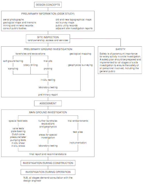
The stages of a ground investigation are given in Table 3.2.

A ground investigation consists, basically, of four main operations:

(1) Study of existing information (known as desk-top study) and preliminary site reconnaissance (site walkabout).
(2) Soil investigation and testing.
(3) Analysis and appraisal of results.
(4) Writing and distribution of soil reports.

In the same way that structural design is a continuous decision-making process and interactive with detailing, other members of the design team, building control and services authorities and the client, so too is the site investigation.

Decisions must be made:

(1) At the start of the survey to determine objectives and methods to achieve the objectives.
(2) On choice of site equipment, where and how best to use the equipment.
(3) On choice of samples to be tested, how to test and interpretation of the test results.
(4) On methods of analysis and recommendations to lead to efficient and economic design and construction.

There should be interaction between the designer and site investigator:

(1) The preliminary design should give the investigator  an indication of the proposed positioning of the struc-
ture on the site, an estimate of foundation loading, any special requirements of basements, services, vibrating or stamping plant and similar information.

(2) The investigator should report periodically to the designer on the findings so that, if necessary, the scope
of the site investigation, the position of the building,  the foundation loading, or the preliminary foundation proposals may be amended.

(3) When the designer has the final site investigation  information the final design can be refined.

(4) The site investigator, given the final design, can refine the report.

(5) Either the designer alone or in collaboration with the
site investigator can then write the final report.

(6) Both the designer and investigator should monitor  the progress of foundation construction and post- construction structural behaviour. This will determine whether the ground conditions were as predicted; whether there were any unexpected excavation problems; whether the magnitude and rate of settlement was as calculated; whether movement joints performed satis- factorily and if the structure remained fully serviceable (i.e. no cracking, undue settlement, etc.). It is difficult for a busy designer to find time to go back and examine past projects, but from long experience it has been found beneficial for progress in foundation design to make time to go back and look critically at past projects.

1. Site survey plan and Study of existing information   1 Site survey planIf a site survey has not been done, or provided by the client, then a topographical survey should be carried out. The survey should show the site location and access, give site boundaries, building lines, position of proposed structure, levels ...(more)

2. Preliminary site reconnaissance and site walkabout    With the above information, presented clearly in an easily digested report, the senior design engineer should visit the site and the immediate neighbourhood to develop a feel for the site. It is sometimes advisable for the senior engineer to visit the site...(more)

 Table 3.2  Stages of a ground investigation.

The Need for Site Investigation: The designer’s need, The contractor’s need, The client’s need.

Tweetear
Site investigations can determine the soil properties and behaviour which will affect the choice and design of the foundations, the method of construction, and can also affect the design of the superstructure as an economic and viable proposition. So the designer, the contractor and the client all have a ‘need to know’.

Site investigations are also necessary prior to carrying out remedial measures to a failed existing foundation.

1 The designer’s need
The following information does not cover all of the designer’s needs but it may assist in producing the most
economical design:

(1) Is the site suitable for the proposed structure, i.e. can it be built economically on the soil or should an alternative location be investigated or has the right price been paid for the land in the first instance?

(2) The load-bearing capacity, settlement and behaviour
characteristics of the soil.

(3) The effect of the new foundation loading on adjoining structures and sub-structures.

(4) The presence of aggressive chemicals in the soil, e.g. high sulfate content which could attack concrete.

(5) Possible changes in settlement behaviour, i.e. future and past mineral extraction, changes in permeability
and moisture content, danger of running sand.

(6) Shrinkage and swelling characteristics, frost heave susceptibility and vibration sensitivity of the soils.

(7) Water-table fluctuations, tidal effects, sub-surface erosion, seasonal and possible long-term variations.

(8) Change in behaviour of the soils due to exposure during foundation construction.

(9) The advisability and economy of ground treatment.


2 The contractor’s need
Similarly the following information assists the contractor in producing the most economical construction:

(1) The stability of the soil during excavation and foundation construction, i.e. soft mud and similar material
will not support heavy piling frames without matting.

(2) The amount of timbering and shoring necessary to support the sides of excavations.

(3) The need for geotechnical processes such as dewatering, freezing and chemical injection.

(4) The presence of any fill material which must be treated or removed, including health and safety implications inherent in dealing with contaminated ground.

(5) The presence of useful excavated material such as broken rock for hardcore, sand for concreting or suitable backfill material.

(6) The suitability of the ground at excavation inverts as a base for poured concrete.

(7) The need for special plant such as rippers and drills for
decomposed rock, or draglines and grabs where the
ground is too weak to support scrapers.

(8) The ground levels relative to a known datum. (This is particularly important for piling operations where pile cut-off levels are specified.)

(9) The need for any special health and safety precautions due to ground conditions, e.g. dangerous shafts, running sand, etc.

(10) The position and other details of existing services, old foundations, etc.

3 The client’s need
The client needs to know:

(1) If it is worth buying the site.

(2) If the foundations will be slow and expensive to construct.

(3) If the soil conditions are such that there are planning constraints on the proposed building.

(4) If the site contains contaminants for which he is legally
responsible.

(5) If the soils on the site are combustible.

(6) If methane gas or other dangerous gases exist beneath the site.

(7) If the site is subject to flooding, subsidence or landslides.

(8) If the developable area is likely to be restricted by mineshafts or other sterilized zones.

4 Site investigation for failed, or failing, existing foundations
Failures of existing foundations are often due to changes in local environment such as re-routing of heavy traffic, leaking drains and water mains, new adjoining construction work (e.g. piling, inadequately shored excavations), new fast-growing tree planting, extra load on sub-soil from new buildings and similar. Before carrying out a soil investigation it is usually worthwhile examining such possible causes of failure in the same way that a desk study and a site walkabout should precede any other soil investigation.

Ground Investigation.

Tweetear
Introduction
This chapter is a summary of experience in dealing with a large variety of ground conditions on which to build a wide range of structures. It may help young engineers who tend to deal with soil properties, geotechnical engineering and superstructure design only – but sometimes give too little attention to ground investigation on which such engineering topics are dependent. This chapter may also be a helpful recapitulation for the experienced engineer.

The ground or sub-strata material needs to be considered as part of the structure, for, like the superstructure, it will be subject to stress, strain and deformation and also possibly to deterioration. If that part of the ‘structure’ is defective or fails then experience shows that it can be the most expensive structural failure to remedy. Furthermore, no matter how well or expertly the superstructure is designed, if the foundation fails it is possible that the superstructure will also fail. Foundation failure is one of the largest causes  of cost claims.

For example, claims for subsidence damage to foundations and buildings following the 1995–96 period
of dry weather in Britain rose to £475 million. It has been stated that piling contractors do not have adequate site investigation details for over half the projects for which they are invited to tender. Before a foundation can be designed it is necessary to know what load the ground can support, how it will react under the load, both in the shortterm and over the structure’s life, and also the effect of this new loading on adjoining structures. Without this information, safe and economic design is difficult and may not be possible. Further, the design should be practical and buildable so the designer should be aware of the contractor’s likely construction methods and possible problems. (Site construction progress can be slow until the foundations are complete, i.e. the building is ‘out of the ground’.)


Before a foundation can be constructed the contractor needs to tender for the project, plan methods of excavation, temporary works and ground treatment, and be forewarned of possible problems, etc., to enable skilful, safe and rapid construction of the foundations. Standard forms of agreement between the design engineer and his client usually state that the designer should exercise ‘reasonable skill and ability’ and meet the standard of a ‘reasonably competent practitioner’. The designer is not expected to be an expert in construction or a specialist in ground treatment. The designer should be wary of non-standard forms with clauses which increase the duty of care to ‘fitness for purpose’. The fact that a cause of failure could not have reasonably been foreseen is no defence with such a clause, nor would professional indemnity insurers accept any obligation.


The ground information is obtained by means of a site investigation. Site investigation, like X-rays and other tests on a sick patient, is not an exact science. The investigation of the ground – as laid down by geological processes, some-times modified by previous construction, mining, etc., and possibly subject to future change – requires detailed planning, careful collection of information, testing and analysis, to be as reliable as possible. Most importantly, it requires the application of engineering knowledge, judgement and experience.

The results need to be reported clearly, precisely and without ambiguity – but it should be appreciated that the result of the most thorough investigation is an  estimate  and not necessarily an accurate forecast. (It has been stated, cynically, that ‘there is only one way to determine the  exact soil conditions and that is to dig it all out, examine it and replace it’ – the designer would then be faced with the problem of building on a fill!)

Even the most thorough, detailed and careful survey and investigation can sometimes lead to false conclusions.

Isolated pockets of peat, meandering channels of loose,  saturated sands, fissures, filled-in shafts and wells, etc., can remain undetected. It is always advisable, therefore, to include in the project estimate a contingency item to cover the possible additional expense of dealing with unforeseen foundation construction difficulties. The engineer should remember that no two samples of soil will have identical properties and that most of the soil tested and reported  on will now be in the testing laboratory and not left on site.

The soil encountered on site is likely to differ (in varying degrees) to that previously tested and due allowance
should be made for this at all stages of the design and  construction process.

Since investigation, analysis and reporting (i.e. interpretation of the results of the investigation) should be based on readily available knowledge and established soil investigation procedures – it may be difficult to plead ignorance in a later dispute over a failure. The designer must obtain the available and relevant data from reliable sources and must interpret that data, not necessarily with over-sophisticated mathematics but with sound judgement and skill.

The costs of a site investigation are low in relation to the overall cost of the project. Engineers can find it difficult to get their client to agree to spending upfront monies resulting in nothing more than a report. The fact that the information contained within this report can be crucial in saving significant sums of money in the design and construction stages of the project is often overlooked. Engineers need toeducate their clients on the costly results of  cheap, inade-
quate soil surveys.

Though a percentage of the capital cost is useful as a preliminary estimate it must be appreciated that it is not a true guide for every site and sufficient funding should be allocated to site investigation to ensure both economic foundation design and construction. Sites and the structures built on them are so varied that it is not possible to  fix firm cost percentages without details of the site and  proposed structure. For example, a low-rise housing estate to be built on well-known and tested London clay overlying Thames ballast is likely to incur less investigation cost  than that for a multi-storey, heavily loaded structure on a suspect, highly variable glacial deposit. Contractors tender- ing for excavation without adequate (or with suspect) site information may gamble, ‘load’ the tender or claim high rates for ‘extras’ and variations.

Clients who object to the cost of a survey or foundation design should be informed of the risks of such cost-cutting.

Clients rarely accept the responsibility of the risk or refuse the additional finance for survey and design.

Delays in construction due to inadequate investigation can easily cost more than any money ‘saved’ by cheap surveys.

Extra-over costs in amending foundation design or construction methods to cope with undetected problems can substantially exceed the total cost of an inadequately funded investigation. Time spent in advising the client to provide adequate funding is therefore worthwhile and often essential. In addition, it is advisable that the client should be made aware that the survey cost begins as an estimate which may need revising as the investigation  proceeds.

Many clients are in a hurry for early handover of the completed project (with the increasing need for early return  on capital investment) and can find time spent on site investigation to be an irksome and unnecessary delay to construction start. The engineer should resist any temptation to skimp the survey and have regard for the client’s long-term interests.

When analysing tenders it is important to have a clear understanding of the kind of sampling and test regime which will actually be required. In the following example (Table 3.1 (a)), Firm 1 appears cheaper initially because their set-up on site and rates of boring and sampling are lower. But when an analysis is undertaken to include the anticipated laboratory testing requirements (Table 3.1 (b)), Firm 2 is the more cost-effective, due to their lower testing rates.


Table 3.1 (a) Site investigation tenders as received.  
(b) Analysis of site investigation tenders

METHODS OF IMPROVING SAFE BEARING PRESSURE OF SOILS.

Tweetear
Sometimes, the safe bearing pressure of soil is so low that the dimensions of the footings work out to be very large and uneconomical. In such a circumstance, it becomes essential to improve the safe bearing pressure, which can be done by the following methods : (i) increasing depth of foundation (ii) compacting the soil (iii) draining the soil (iv) confining the soil (v) grouting and (vi) chemical treatment.

1. Increasing depth of foundation. It has been found that in granular soil, the bearing capacity increases with the depth due to the confining weight of overlying material. However, this is not economical since the cost of construction increases with the depth. Also, the load on the foundation also increases with the increase in the depth. The method is useful only when better bearing stratum is encountered at greater depth.

2. Compaction of soil. It has found that compaction of natural soil deposits (loose) or man-made fills results in the improvement of bearing capacity and reduction in the resulting settlements. Compaction of soil can be effectively achieved by the following means:

(a) Ranmining moist soil. The foundation, soil is moistened and then compacted with the help of hand rammers or mechanically operated frog rammers or vibratory rollers. The voids of the soil are very much reduced, resulting in the reduction in settlements.

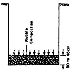
(b) Rubble Compaction into the soil. A Iayer of 30 to 45 cm thick well graded rubble is spread over the foundation level (Fig. 2.26) and weIlrammed. If this layer of rubble gets buried in the soil (specially when it is very loose) another Iayer of 15 cm thick rubble is spread and well rammed manually. This results in an increase in the bearing value of the soil

FIG. 2.26  RUBBLE COMPACTION INTO THE SOIL.


(c) Flooding the soil. The bearing pressure of very loose sands can be increased by flooding the soil. The method is very effecilve in improving the safe bearing pressure of dune sands, which cannot otherwise be effectivety compacted. The Author has an experience of improving the bearing power of desert soils by this method at  many locations where it was required to support heavy loads.

(d) Vibration. Heavy vibratory rollers and compactors may compact a Iayer of granular soils to a depth of 1 to 3 m. If the method of flooding and then vibration is used, sandy soil can be very effectively compacted, resulting in increased safe bearing power and decreased settlements when super-structure loads come on the soil. After flooding the soil, so that moisture penetration is al least 1 to 2 m, form vibrators or platform vibrators (about 1 m x 1.5 m base area, with a pair of eccentrically loaded motors) can be silded on the sand surface with the help of two labourers. A large area can be covered by this process, without the help of sophlsticated vibrating equipment.

(e) Vibroflotation. It is a commercial method which combine the effect of vibration and jetting. A heavy cylinder, known a vibroflot is inserted in the ground (soil) while the cylinder vibrates due to a rotary eccentric weight. A water jet on the tip of the vibro flot supplies a large amount of water under pressure. As the vibro flot sinks, clean sand is added into a crater that develops on the surface. The method is very useful when foundation is required to support heavy loads spread over a greater area.

(f) Compaction by pre-loading. This method is useful when he footing is founded on clayey solis which result in long term settlements. Pre-loading results in accelerated consolidation, so that settlements are achieved well before the actual footing is laid. The load used for this process is removed before the construction of the footing.

(g) Using sand piles. This method is very useful in sandy soil or soft soils. Hollow pipes are driven in the ground, at close interval. This results in the compaction of soil enclosed between the adjacent pipes. These pipes are then gradually removed, filling and ramming sand in the hole, resulting in the formation of sand piles.

3. Drainage of soil. It is a weIl known fact that presence of water decreases the bearing power of soil, specially when it is saturated. This is because of low shearing strength of soil in presence of excess water. Drainage results in decrease in the voids ratio, and improvement of bearing power.

4. Confining the soil. Sometimcs the safe bearing pressurc of the soil is low because of settlements resulting due to the lateral movement of loose granular soil. Such a tendency of lateral movement can be checked by confining the soil, outside ihe peritneter of foundation area, by driving sheet piles, thus forming an enclosure and confining the soil.

5. Grouting. This method is useful in loose gravels and fissured rocky strata. Bores holes in sufficient numbers are driven in the ground and cement grout is forced through these under pressure. The cracks, voids and fissurcs of the strata are thus filled with the grout, resulting in the increase in the bearing value.

6. Chemical treatment. In this method, certain chemicals are grouted in the place of cement grout. The chemical should be such that it can solidify and gain early strength.

Dutch cone test - SITE EXPLORATION.

Tweetear
This test is used for getting a continuous record of the resistance of soil by penetrating steadily under static pressurc a cone with a base of 10cm^2 (3.6 cm in dia.) and an angle of 60º  at vertex. The cone is carried at the lower end of a steel driving rod which passes through a steel tube (mantle) with external diameter equal to the base of the cone. Either the cone or the tube, or both together can be forced into the soil by means of jack. To know the cone resistance, the cone along is first forced down for a distance of 8 cm and the maximum value of resistance Is recorded. The steel tube is then pushed down upto the cone, and both together are further penetrated through a depth of 20 cm to give the total of cone resistance and the frictional resistance along the tube.

The Cone test is considered very useful in determining the bearing capacity of pits in cohesionless soils, particularly in fine sands of varying density. The cone resistance qc (kg/cm^2) is approximately equal to 5 to 10 times the penetration resistance N.

Standard Penetration Test - SITE EXPLORATION.

Tweetear
The test (IS : 2131—1963) is performed in a clean hole, 55 to 150 mm in diameter. A casing or drilling mud may be used to support the sides of the hole. A thick wall split tube sampler, 50.8 mm outer dia. and 35 mm internal dia. is driven into the undisturbed soil at the bottom of the hole under the blows of 65 kg drive weight with 75 cm free fall: The minimum open Iength of the sampler should be 60 cm. The sampler is first driven through 15 cm as a seating drive. It is further driven through 30 cm and the number of blows required for this are counted. This number of blows is termed as penetrarion resistance N.

In very fine, or sitly, saturated sand, an apparent increase in resistance occurs. Terzaghi and Peck have recommended the use an equivalent penetration resistance Ne, in place of the actually observed value of N, when N is greater than 15. Ne is given by the following relation:


Terzaghi and Peck’s empirical charts for determining nct bearing pressure qp for footing on sand depend on B and N value, to limit maximum settlement of individual footing to 2.5 cm and differential settlement of 2 cm, assuming that a differential settlement of 2 cm can be tolerated by most of the ordinary structures. The empirical relations are represented by the following equation:

The standard penetration test is very useful for the design of rafts. The safe bearing value for rafts may be taken as smaller of the values of q1 and q2 given bellow:

PENETRATION TESTS - SITE EXPLORATION.

Tweetear
These tests involve the measurements of the rcsistance to penetration of a sampling spoon, a cone or other shaped tool under dynamic or static loadings. The resistance is empirically correlated with sorne of the engineering properties of soil, such as density index, bearing capacity etc. Two commonly used penetration tests are

(i) Standard penetration test, The test (IS : 2131—1963) is performed in a clean hole, 55 to 150 mm in diameter. A casing or drilling mud may be used to support the sides of the hole....

(ii) Dutch cone test. This test is used for getting a continuous record of the resistance of soil by penetrating steadily under static pressurc a cone with a base of 10cm^2 (3.6 cm in dia.) and an angle of 60º  at vertex....

Limitations of plate load test - FOUNDATION SITE EXPLORATION.

Tweetear
The plate load test has the following limitations:

1. The test results reflect only the character of the soil located within the depth Iess than twice the width of bearing plate (corresponding to a pressure bulb of one-tenth of the loading intensity at the test plate). Since the foundations are generally larger, the settlement and resistance against shear failure will depend on the properties of a much thicker stratum.

2. It is essentially a short duration test, and hence the test does not give the ultimate settlement, particularly in the case of cohesive soils.

3. Another limitation is the effect of the size of foundation. For clayey soils the ultimate pressure for a large foundation is the same as that for the test plale. But in dense sandy soils, the bearing capacity increases with the size of the foundation, and the tests on smaller size bearing plates tend to give conservative values.

PLATE LOAD: Safe bearing pressure on permissible settlement - FOUNDATION SITE EXPLORATION.

Tweetear
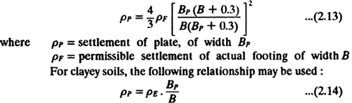
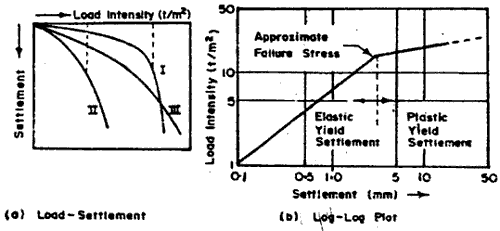
The safe bearing capacity determined above is on the basis of shear failure. The settlement of the footing also governs the bearing capacity of soil. Such a bearing pressure can be obtained from the load settlement curve, corresponding to the desired settlement of the test plate. Generally, the permissible settlements of footings are specified in the Codes. The corresponding settlement of the test plate can be found from the following relationship applicable for granular soil:


The net loading intensity corresponding to settlement ρp, is then determined from Fig. 2.24. The safe bearing pressure is then lesser of the following two values: (i) safe bearing capacity found on the basis of shear failure, and (ii) net loading intensity corresponding to settlement ρp, of the plate.

 FIG. 2.24  LOAD SETTLEMENT CURVES.

PLATE LOAD: Test procedure - FOUNDATION SITE EXPLORATION.

Tweetear
The plate is firmly seated in the hole, and if the ground is slightiy uneven a thin layer of sand is spread underneath the plate. The load is applied with the help of a hydraulic jack (preferably with the remote control pumping unit), in convenient increments, say of about one-fifth of the expected safe bearing capacity or one-tenth of the ultimate bearing capacity. Settlement of the plate is observed by 2 dial gauges fixed at diametrically opposite ends and supported on a suitable datum bar. The dial gauges should have a sensitivity of 0.02 mm. Settlement should be observed for each increment of load after an interval of 1, 4, 10, 20, 40 and 60 minutes and thereafter at hourly intervals until the rate of settlement becomes less than 0.02 mm per hour. After this, next load increment is applied. The maximum load that is to be applied corresponds to 1 1/2 times the eslimated ultimate load or to 3 times the proposed allowable bearing pressure.

The water table has marked influence on the bearing capacity of sandy or gravelly soil. If the water table is already above the, level of footing, it should be lowered by pumping and the bearing plate seated after the water table has been lowered just below the footing level. Even if the water table is located above 1 m below the base level of the footing, the load test should be made at the level of water table itself.

The load intensity and settlement observations of the plate load are plotted as shown in Fig. 2.24 (a). Curve I corresponds to general shear failure and curve II corresponds to local shear failure. Curve III is a typical of dense cohesionless soils which do not show any marked shear failure under the loading intensities of the test.
When the load settlement curve [Fig. 2.24 (a)] does not indicate any marked breaking point, failure may alternatively be assumed corresponding to a settlement equal to one-fifth of the width of the test plate. In order to determine the safe bearing capacity it would be normally sufficient to use a factor of safety of 2 or 2.5 on utlimate bearing capacity.

 FIG. 2.24  LOAD SETTLEMENT CURVES.

PLATE LOAD TEST - FOUNDATION SITE EXPLORATION.

Tweetear
Plate Load Test is a field test to determine the ultimate bearing capacity of soil, and the probable settlement under a given loading. The test esssentially consists in loading a rigid plate (usually of steel) at the foundation level, and determining the settlements corresponding to each load increment. The ultimate bearing capacity is then taken as the load at which the plate starts sinking at a rapid rate. The method assumes that down to the depth of influence of stresses, the soil strata is reasonably uniform.


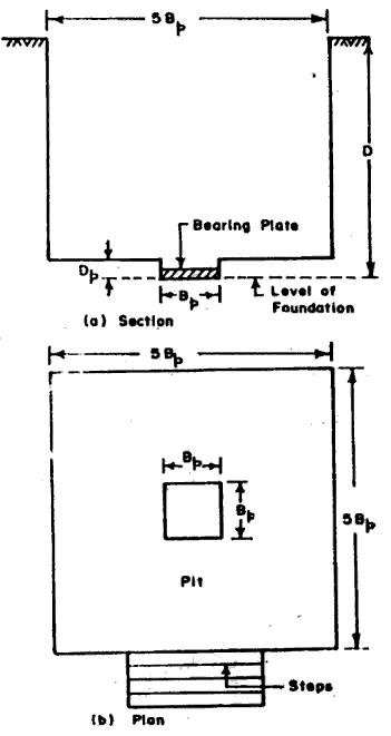
FIG.  2.21  TEST PIT.


The beanng plate is square, of minimum recommended size 30 cm square, and maximum size, 75 cm square. The plate is machined on sidcs and edges, and should have a thickness sufficient to withstand effectively any bending stresses that would be caused by the maximum anticipated load. The thickness of steel plate should not be less than 25 mm.

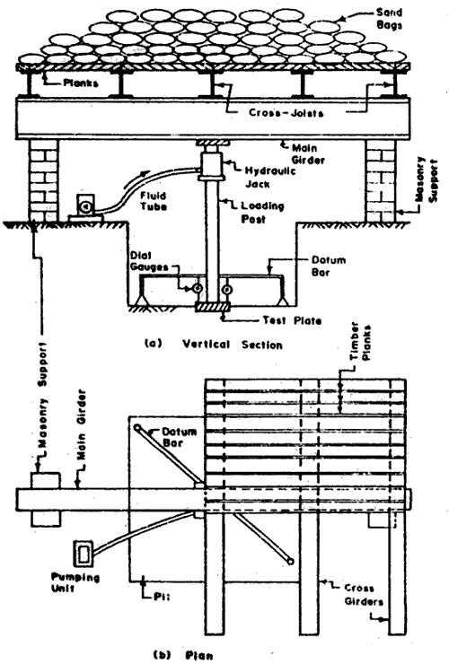
FIG. 2.22 PLATE LOAD TEST: REACTION BY GRAVITY LOADING.

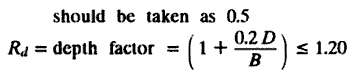
The test pit width is made five times the width of plate (Bp). At the centre of the pit, a small square hole is dug whose size is equal to the size of the plate and the bottom level of which corresponds to the level of actual foundation (Fig. 2.21). The depth Dp, of the hole should be such that


The loading to the test plate may be applied with the help of a hydraulic jack. The reaction of the hydraulic jack may be borne by either of the following two methods:

(a) gravity loading platform method,
(b) reaction truss method.

In case of gravity loading method a platform is constructed over a vertical column resting on the plat form, and the loading is done with the help of sand bags, stones or concrete blocks. The general arrangement of test set-up for this method as shown in Fig. 2.22. When load is applied to the test plate, it sinks or settles. The settlement of the plate is measured with the help of sensitive dial gauges,. For square plate, two dial gauges are used. The dial gauges are mounted on independently supported datum bar. As the plate settles, the ram of the dial gauge moves down and settlement is recorded. The load is indicated on the load-gauge of the hydraulic jack.


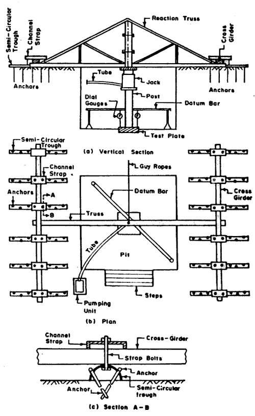
Fig. 2.23 shows the arrangement when the reaction of the jack is borne by a reaction truss. The truss is held to the ground through soil anchors. These anchors are firmly driven in the soil with the help of hammers. The reaction truss is usually made of mild steel sections. Guy ropes are used for the lateral stability of the truss.

Note. In olden days, the loading on the plate was made with the help of gravity loading consisting of weighed sand bags on a platform constructed over the central loading column. The settlement of the plate was measured with the help of a dumpy level. Such an arrangement is crude since the settlements are not measured upto the desired accuracy and the arrangement gets disturbed during the incremental loading. Certain mishaps have also been reported due to the tilting of the loading platform (Fig.  2.22) or by reaction truss (Fig. 2.23).

FIG.  2.23  PLATE LOAD TEST: REACTION BY TRUSS.

⇒ Test procedure.
⇒ Safe bearing pressure on permissible settlement.
⇒ Limitations of plate load test.