|
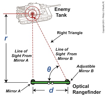
We left off with an artillery soldier spotting an enemy tank in the distance. Luckily, he’s got an optical rangefinder at his disposal to measure the distance between them and crank out an accurate shot. His first action is to peer through the rangefinder’s eyepieces, rotating the adjustable mirror on the right eyepiece until the tank comes into focus. The two lines of sight provided by the left and right eyepieces of the rangefinder form a right triangle due to the parallax effect. One of the angles in this triangle is designated on the illustration by the angle θ, and that’s the angle we’ll be working with. The fact that a right triangle exists means the distance, r, to the tank can be easily measured using principles found in trigonometry, a branch of mathematics that addresses the properties of triangles, hence, the prefix tri in its name. Tangent, and other trigonometric functions like sine and cosine, relate the angles of a right triangle to the ratios of the lengths of the sides of the triangle. In our case we’re concerned with the tangent, which is simply the value that’s derived by dividing the length of the side opposite to the angle θ by the length of its adjacent side. This value can be found in most trigonometry textbook tables, but is most easily found by using a calculator. Simply enter the angle θ‘s value, then press the TAN button. So how does the artillery soldier determine θ‘s value? With the tank in clear focus, it’s easily measured with an indicator gauge attached to the adjustable mirror near the right eyepiece on an optical rangefinder. Our soldier reads the gauge and determines that θ is equal to 89.935°, so the tangent of θ is equal to: tan(θ) = tan(89.935°) = 881.473 Now that we’ve determined the values for d and the tangent of the angle θ, we can plug those numbers into our equation to determine r, the distance to the enemy tank using the equation, r = d × tan(θ) Plugging in numerical values, the equation becomes, r = 3 feet × 881.473 = 2644.419 feet The distance to the tank is 2644.419 feet. Next time we’ll see how the peculiarities of the tangent function place limitations on the accuracy of optical rangefinders over extremely long distances. ____________________________________
|
How An Optical Rangefinder Uses Trigonometry
February 23rd, 2015What’s Inside an Optical Rangefinder
February 13th, 2015|
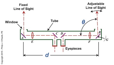
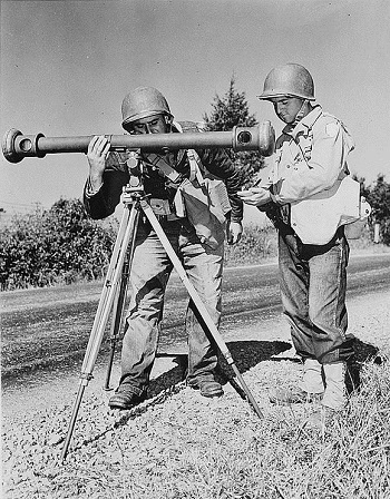
Last time we covered the mirrors found inside an optical rangefinder. Today we’ll discuss its other components, magnifying lenses E and F and the indicator gauge, G. See Figure 1. Figure 1 Magnifying lenses E and F are positioned in such a way that the two horizontal lines of sight reflecting off mirrors C and D pass through them on their way to mirrors A and B. Lenses E and F are adjustable, allowing the viewer to manipulate them until the distant image being viewed is seen in clear focus through both eyepieces, just as would happen with binoculars. To see the rangefinder in action let’s go out to the battlefield, where it’s routinely used. A soldier notices an enemy tank off in the distance. To make an accurate hit with his artillery he must determine the distance r from his position to the tank. The soldier in charge of this task observes the tank through the rangefinder’s eyepieces and manually adjusts lenses E and F until it comes into focus. He then adjusts the rangefinder’s mirror B until the line of sight extending from it converges on the tank along with the fixed line of sight from mirror A as shown in Figure 2. When the two images converge a right triangle is formed, and as we learned in a previous article, this fact will enable us to calculate r by using trigonometry with this formula: r = d × tan(θ) We already know that the value of d, the distance between mirrors A and B, is three feet. All that is left to be determined is the angle θ that’s formed between adjustable mirror B‘s forward line of sight out the tube’s opening and the horizontal line of sight between D and B. The last component within an optical rangefinder to be discussed is the indicator gauge, notated as G in Figure 1. This gauge is attached to mirror B inside the tube and is used to measure the angle θ that’s produced as the mirror is adjusted. When the lines of sight from mirrors A and B converge and the tank comes into clear view through the eyepieces, the value of θ can be read on the gauge’s numerical graduated scale, which is located on the exterior of the tube. Next time we’ll see how trigonometry and the study of right triangles prove indispensable when measuring distances with an optical rangefinder. ____________________________________
|
The Mirrors Inside an Optical Rangefinder
February 6th, 2015|
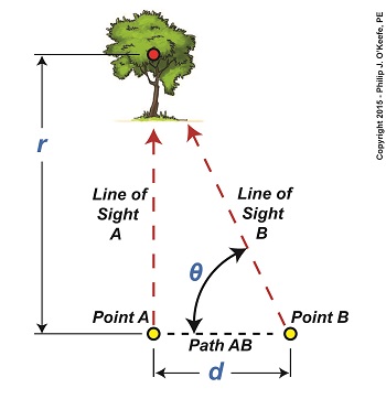
Last time we touched on the fact that humans require instruments to facilitate the optical measurement of distance to faraway objects, such as is represented by r in Figure 1. Figure 1 Today we’ll take a look at the mirrors inside an optical rangefinder, one of the devices that’s commonly used to measure great distances. The internal workings of an optical rangefinder are shown in Figure 2. Figure 2 The rangefinder’s body is a straight tube containing fixed mirrors, A, C, and D, and an adjustable mirror, B. Mirrors A and B in Figure 2 are analogous to Points A and B in Figure 1. For the sake of our example, we’ll say that the distance d in Figure 2 is equal to the distance d in Figure 1. This distance is three feet. The rangefinder functions similarly to a pair of binoculars, but with a twist — literally. Its four internal mirrors redirect the straight-ahead perspective that’s provided by the eyepieces into sideways orientations. Sight is deflected by mirrors C and D off to the left and right, respectively, as represented by red dashed lines. Finally, the lines of sight are once again aligned into straight-ahead orientations as they reflect off mirrors A and B and are guided out the openings at either end of the tube. Adjustable mirror B‘s line of sight is positioned at an angle that’s represented by the Greek letter θ, a symbol commonly used to represent angles in mathematics, engineering, and science. This angle is formed between mirror B’s line of sight and the horizontal line of sight traversing the expanse between mirrors D and B. The reason mirror B is an adjustable mirror is so that the line of sight extending from the opening at its location can converge into the line of sight provided by mirror A. Mirror B is manually manipulated until the image seen through it becomes one with A‘s image. Until this convergence takes place two separate images are seen through A and B. Next week we’ll see what happens when the images converge, and we’ll cover the remaining components within an optical rangefinder, items E, F, and G. ____________________________________
|
Parallax and Trigonometry
January 26th, 2015|
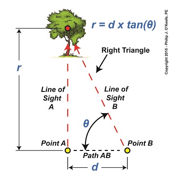
We’ve been working on a way to calculate the distance to a tree situated blocks from our viewing point. Flying raptors, such as our beloved bald eagle, wouldn’t find this in the least bit challenging. They’re able to accurately judge distances due to their special shape-shifting eye lenses which are capable of actually changing curvature spontaneously. But human physiology isn’t equipped for this task, so we’ll have to employ other methods. Today we’ll see how a branch of mathematics known as trigonometry comes into play. Referring to the illustration, we’d like to calculate the distance, r. You’ll note that a right triangle is formed by Line of Sight A, Path AB, and Line of Sight B. As mentioned in our last blog, right triangles are special because the relationship that exists between their sides and their internal angles is well defined within mathematics. In fact, we can calculate r by using this trigonometric formula, r = d × tan(θ) where d is the length of Path AB, θ is the angle between Line of Sight B and Path AB, and tan(θ) is the trigonometric function known as the tangent. Tangent, and other trigonometric functions like sine and cosine, relate the angles in a right triangle to the ratios of the lengths of the sides of the triangle. If we know two of the variables present in the equation presented above, we can determine the third, and the fact that there’s a right triangle present makes that task so much easier. As things stand now we have two unknowns, d and θ. As pointed out last week, the distance, d, is short, so we’ll use a tape measure to determine its length. Let’s say it measures out to be three feet. Now we need to solve for the angle θ that’s formed between Path AB and Line of Sight B. That’s a bit more challenging. There are a number of devices that can be used to measure θ, including a handheld magnetic compass. However, using a compass often yields inaccurate results, thereby increasing the likelihood of mistakes. A more accurate device to use would be an optical rangefinder, as shown below. The optical rangefinder is a device that’s often used in the military to measure long distances by using the principle of parallax. It functions much like binoculars do, but with a twist, literally, as we’ll see next time. ____________________________________
|
Using Parallax to Measure Distance
January 19th, 2015|
Last time we introduced an optical effect known as the principle of parallax. Today we’ll get a step closer to seeing how it’s instrumental in measuring distances. For our example we’ll be viewing a point on a tree several blocks away. Since we can’t measure the distance, r, to the tree directly by using a tape measure, we’ll have to use another approach that is made available to us through the principle of parallax. The first step to doing this is to establish two different lines of sight to the red dot on the tree. For our example these will originate at Points A and B, which are both viewing the same spot. Line of Sight A extends straight from Point A to the red spot, while Point B, which is situated only a few feet to the right of A, will provide us with a slanted line of sight to it. We’ll refer to the path between Points A and B as Path AB, which is represented by a black dashed line and has a length, d. You may have noticed from the illustration that Line of Sight B, because it lies on a slant relative to Line of Sight A, provides us with an internal angle, θ, relative to Path AB. This relationship is in fact required to exist if we are to use the principle of parallax, and you’ll see why later. Another requirement is that Path AB must be at a right angle to Line of Sight A, which it is. The illustration bears this out by the fact that a right triangle is formed when Lines of Sight A, B, and Path AB intersect. Right triangles are generally regarded as special within mathematics, but they are particularly special when applying the principle of parallax. The presence of a right triangle enables us to use a branch of mathematics known as trigonometry to correlate the triangle’s angles to the ratios of the lengths of its sides. In other words, we can calculate r by using trigonometry if we are able to measure d and θ. We’ll see how that calculation is done next time. ____________________________________
|
The Principle of Parallax
January 8th, 2015|
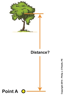
We’ve been looking at the indirect methods employed by scientists through the ages as they struggled to determine the distance of our Earth from its sun. Today we’ll take a look at one of those indirect methods, known in scientific circles as the Principle of Parallax. Parallax is an optical effect which results in a three dimensional view of the world as seen through our eyes. Because our eyes are spaced a distance apart from each other on the relatively flat surface of our face, each of them will perceive an object along a different line of sight and thus offer differing perspectives. Our brain makes use of the parallax phenomenon to automatically process these differing perspectives into a single image, along with providing us with a three dimensional view of the object, something that comes in handy when negotiating our physical world. As an example, let’s say you’re sitting at the kitchen table staring at a cup of coffee. Your left eye sees the cup from one perspective, your right eye another. To prove it, cover each of your eyes in turn as you look at it. You’ll see that the perspective changes between your two eyes. These two perspectives are processed by your brain into an internal calculation which enables you to adjust your muscle response accordingly. The result is that you are able to deftly pick up the cup of coffee and bring it to your lips rather than clumsily toss it to the floor. Parallax is at work when viewing objects both near and far. Consider Figure 1. Suppose we want to measure the distance from Point A to a tree several blocks away. That’s too far away to use a tape measure, but we can employ the parallax phenomenon and trigonometry, the study of angles, to easily determine the distance. We’ll get a step closer to doing that next time.
____________________________________
|
Kepler’s Third Law Of Planetary Motion
December 31st, 2014|
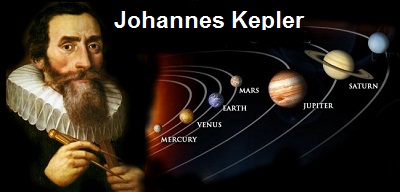
Edmund Halley was faced with a real puzzle when he began his quest to determine the distance of Earth from the sun. One of the pieces to solving that puzzle came from the work of a German mathematician, astronomer and astrologer named Johannes Kepler. Early in the 17th Century, Kepler spent a lot of time observing the planets in our solar system as they orbited the sun. He discovered that by taking note of the time it took for a planet to make one orbit around the sun, he could determine its relative distance from it. He then compared his findings with other planets, noting the time it took for each to make this same journey. His discovery would come to be known as Kepler’s Third Law of Planetary Motion. But what exactly is meant by a planet’s “relative distance from the sun”? In essence, it means that interplanetary distances, like just about everything else, are relative. Put another way, heavenly bodies can be said to be a distance X relative to another heavenly body if you establish a value for X, whether it’s numerical or otherwise. In Kepler’s case, X would be the unknown value of a so-called astronomical unit (AU), where one AU is equal to the unknown distance from Earth to the sun. Represented in equation form, this distance is: rEarth-sun = 1 AU This relative marker of distance could then be used to show how far the other planets are from the sun, relative to Earth’s distance from the sun, the AU. Kepler’s astronomical unit is simply a placeholder term for an unknown quantity, similar to any other unknown variable that might be used in an algebraic equation. For example, Kepler observed the orbits of Venus and Mars and determined their relative distances to the sun to be: rVenus-sun = 0.72 × 1 AU = 0.72 AU rMars-sun = 1.5 × 1 AU = 1.5 AU In other words, Venus’ distance from the sun is just under three quarters of Earth’s and Mars is one and a half times Earth’s distance from the sun. In this way, Kepler was able to determine the relative distances from the sun in AU for all the observable planets in our solar system. Kepler felt sure that one day scientists would be able to accurately measure Earth’s distance from the sun, and when they accomplished this they could employ his astronomical unit system to determine distances between other planets in our solar system and the sun. Next time we’ll introduce the principle of parallax and see how Halley used this optical effect to devise a method for assigning a value to Kepler’s unknown AU. ____________________________________ |
How Far Away is the Sun?
December 24th, 2014|
Astronomers tell us that the sun is approximately 93,000,000 miles from Earth. Since no direct method of measuring this distance exists, how did scientists determine this? They had to resort to indirect methods. In the early 18th Century, British astronomer, mathematician and physicist Edmund Halley, of Halley’s Comet fame, devised a method to measure the distance between Earth and its sun with reasonable accuracy. His method was based in part on an optical effect known as the principle of parallax, which had been discovered more than 2000 years ago by Greek astronomer Hipparchus when he also employed it to try and determine that same distance. Halley also employed the ideas of 17th Century German mathematician, astronomer, and astrologist Johannes Kepler. Kepler’s work on planetary motion, in particular the geometry of planetary orbits in our solar system, were vital to Halley’s distance measuring method. Next time we’ll see how Kepler’s Third Law of Planetary Motion brought Halley one step closer to methodology that would determine the distance of our home planet to its sun. _______________________________________
|
Thanks For the Gift, Sir Isaac
December 19th, 2014|
It’s the season of giving. The time of year we’re most apt to remember our loved ones and those who provide service to us by bestowing them with gifts. It’s a time when traditions and nostalgia for things past may cause us to get emotional. We celebrate many holidays throughout the year, memorializing veterans, family members, political leaders, but none to celebrate the scientist, the inventor, those individuals who have graced mankind with their insights, courage, and perseverance to go beyond the ordinary, to dare to understand things most would believe are beyond human understanding. The accomplishments of these uncelebrated figures have elevated humanity time and again. Where are their days? The scientist in me would like to see a Sir Isaac Newton Day, an Albert Einstein Day, Madame Curie Day, Stephen Hawking Day — Americans could use more days off to relax. And when the youngsters in our charge ask, “Who’s Einstein? Who’s Madame Curie?”, we could regale them with tales of the heroes that contributed to our understanding of the workings of the universe. Perhaps the information might prove inspirational enough to the receptive young mind to light the fire of exploration within them. Scientists throughout history have given us many gifts, the type of gifts that change things forever. They may not be what first comes to mind when imagining heroes, but in my mind they’re nothing less. Wishing you all an inspirational and happy holiday season and New Year! _______________________________________
|
Gravity and the Mass of the Sun
December 12th, 2014|
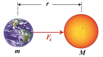
As a young school boy I found it hard to believe that scientists were able to compute the mass of our sun. After all, a galactic-sized measuring device does not exist. But where there’s a will, there’s a way, and by the 18th Century scientists had it all figured out, thanks to the work of others before them. Newton’s two formulas concerning gravity were key to later scientific discoveries, and we’ll be working with them again today to derive a third formula, bringing us a step closer to determining our sun’s mass. Newton’s Second Law of Motion allows us to compute the force of gravity, Fg, acting upon the Earth, which has a mass of m. It is, Fg = m × g (1) Newton’s Universal Law of Gravitation allows us to solve for g, the sun’s acceleration of gravity value, g = (G × M) ÷ r2 (2) where, M is the mass of the sun, r is the distance between the sun and Earth, and G is the universal gravitational constant. You will note that g is a common factor between the two equations, and we’ll use that fact to combine them. We’ll do so by substituting the right side of equation (2) for the g in equation (1) to get, Fg = m × [(G × M) ÷ r2] then, using algebra to rearrange terms, we’ll set up the combined equation to solve for M, the sun’s mass: M = (Fg × r2) ÷ (m × G) (3) At this point in the process we know some values for factors in equation (3), but not others. Thanks to Henry Cavendish’s work we know the value of m, the Earth’s mass, and G, the universal gravitational constant. What we don’t yet know is Earth’s distance to the sun, r, and the gravitational attractive force, Fg, that exists between them. Next time we’ll introduce some key scientists whose work contributed to a method for computing the distance of our planet Earth to its sun. _______________________________________
|
